
18 Years of public-private partnership for developing post-combustion CO2 capture at Technology Centre Mongstad in Norway (2024)
G.M. de Koeijera*, E. Gjernesb, S. Pedersena, C. Ehrhornc, S. Jouenned, V. Pugnetd, R. Cadourse, S.I. Sembb, M.I. Shahf
aEquinor, Forusbeen 50, 4035 Stavanger, Norway
*Corresponding author. Tel.: +47 90981326, E-mail address: gdek@equinor.com
bGassnova SF, Dokkvegen 11, 3920 Porsgrunn, Norway
c A/S Norske Shell, Løkkeveien 103, 4007 Stavanger, Norway
dTotalEnergies OneTech, CSTJF EB 437, Avenue Larribau, F-64018 Pau Cedex, France
eTotalEnergies OneTech, Tour Coupole, 2 place Jean Millier, 92078 Paris La Défense Cedex, France
fTCM DA, Mongstad 71A, 5954 Mongstad

Abstract
This paper has reviewed the 18 years of technology development done at Technology Centre Mongstad (TCM) from the perspective of the companies financing its activities. TCM is the world’s largest and most flexible open test center for post-combustion CO2 capture technologies. The current owners of TCM are Gassnova (representing the Norwegian State), Equinor, Shell and TotalEnergies. The ambitions for this public-private partnership were and still are:
- Develop technologies for CO2 capture capable of wide national and international deployment
- Reduce cost and technical, environmental and financial risks related to large scale CO2 capture
- Test, verify and demonstrate CO2 capture technology owned and marketed by vendors
- Encourage the development of a market for such technology
The first achievement was the design, construction and start-up. An important milestone was the world’s first emission permit that included the health risk due to nitrosamines and nitramines. Next 8 commercial technology vendors have matured their technology in the large demonstration units, increasing the competition and diversity. Moreover, many open campaigns have contributed to significant knowledge sharing. Nearly 70 scientific papers provide solid evidence on benchmarks, energy performance, emissions, degradation, corrosion, CO2 product composition and cost reduction. TCM has had cooperation with a multitude of universities and research institutes. Finally, the site for emerging technologies has increased the diversity even more by allowing a larger variety of less mature technologies to be developed. Most of the initial ambitions are fulfilled, and there are still opportunities for continuing supporting CO2 capture development at TCM.
Keywords: post-combustion; amine; Mongstad; review; ambitions; public-private partnership
1. Introduction
Technology Centre Mongstad (TCM) is the world’s largest and most flexible open test center for post-combustion CO2 capture technologies. The idea to build such a center was initiated in 2006 in relation to a new Combined Heat and Power (CHP) plant at Equinor’s Mongstad refinery on the West coast of Norway. The investment decision was taken in 2009 and operations started in 2012. This public-private partnership will celebrate 18 years with technology development experience in 2024. The aim of this paper is to review the technology development done from the perspective of the companies financing its activities, which will be referred as owners in this paper. The current owners of TCM are Gassnova (representing the Norwegian State), Equinor (previously Statoil and StatoilHydro), Shell and TotalEnergies (previously Total). As part of their broader CCS strategies, the latter three companies are possible buyers and operators of capture technology from various vendors. The owners’ group has changed over time. Gassnova, Equinor and Shell have been owners all 18 years. In the design phase up to the investment decision DONG (now Ørsted) and Vattenfall were also partners. Sasol joined during construction and left after 5 years of operation. TotalEnergies joined in 2017.
In a paper from 2009 [1], the owners’ ambitions were published. These were and still are as follows:
- Develop technologies for CO2 capture capable of wide national and international deployment
- Reduce cost and technical, environmental and financial risks related to large scale CO2 capture
- Test, verify and demonstrate CO2 capture technology owned and marketed by vendors
- Encourage the development of a market for such technology
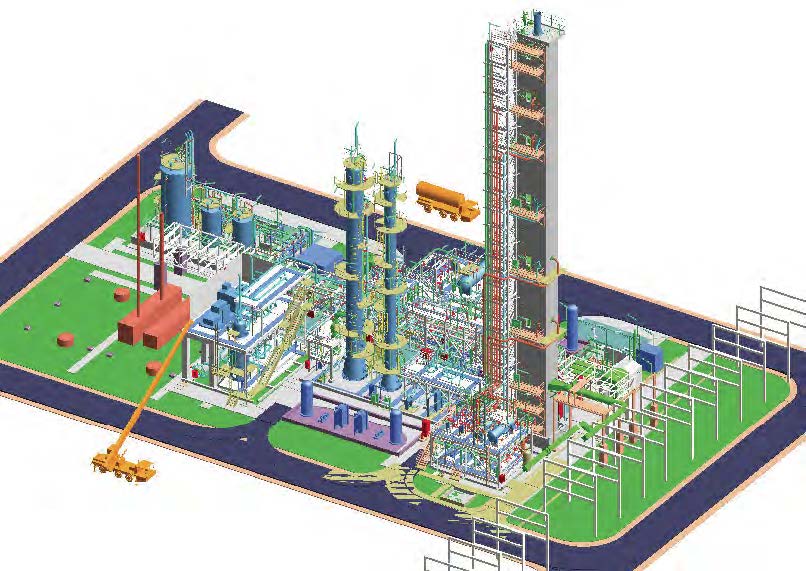
As can be read in this paper, most of these ambitions are fulfilled, while there are still viable options for more. TCM has contributed actively to the development of CO2 capture technologies and the market. In the following chapters, the main results will be discussed one by one, finalized by a discussion on how the owners assess the value of TCM. A general aim of TCM was to get high quality and well endorsed numbers. TCM has called upon experts with high and specialized competence. TCM uses more sensors, higher accuracy measurements and more methods than usual, including multiple reviews and independent assessments. Over time, a multitude of universities and research institutes have cooperated with TCM. The owners hope that this extra effort will ultimately contribute to increased trust in CO2 capture as a climate change mitigation technology. An important boundary condition for all the results was that an attractive cost sharing model for all contributors and stakeholders was established. Most test campaign costs are split between TCM owners and vendors. Some campaigns have also been partly funded by Norwegian and European R&D programs. The US Department of Energy has supported various campaigns through a US-Norway Memorandum of Understanding. There has been development towards larger contribution from technology vendors. To illustrate the size and ambition of TCM, its annual operating costs are in 2023 around 200 million NOK [2]. And below in Figure 1 a photograph and a 3D rendering of TCM is shown to illustrate the size and complexity.
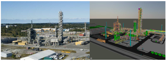
Fig. 1. Picture (source: TCM DA) and 3D model image of TCM.
2. Two big demonstration units successfully designed, constructed, and operated
The design of TCM consists of an amine unit, a chilled ammonia process (CAP) unit, utilities, and a site for emerging technologies (SET). The flue gas is delivered by pipes on a piperack from a Combined Heat and Power plant (CHP, up to 3.6 vol% CO2 and 60 000 Sm3/h) and a Residue Fluidized Catalytic Cracker (RFCC, up to 13 vol% CO2 and 50 000 Sm3/h with SOx, NOx and particulates). All elements were successfully designed, constructed, and put into operation in the period 2009-2014. The first start-up was in August 2012. More detailed description of the results and design can be found later in this paper. A list of public papers and reports can be found at the TCM website [3]. Due to all these features, TCM was and still is the world’s largest and most flexible test site for post-combustion CO2 capture. An important inspiration for TCM’s amine unit was the Esbjerg pilot in Denmark used for the CASTOR and CESAR projects [4]. TCM’s aim was to provide a meaningful scale-up and increase in flexibility relative to the Esbjerg pilot.
The amine unit was designed by SLB Capturi (formerly Aker Carbon Capture, and previously Aker Clean Carbon at the time of design and construction) and built by Aker Solutions. The design of the system was based on the use of monoethanolamine (MEA) as the primary solvent, with the flexibility to accommodate alternative solvents. Due to the varying CO2 concentrations, the flow rates of CO2 entering the absorber differ significantly, necessitating adjustments to the solvent circulation rate. To address this, two strippers were designed and constructed. The smaller stripper has a capture capacity of up to 3.5 tonnes CO2/h, primarily handling emissions from the combined heat and power (CHP) unit, while the larger stripper, with a capacity of 8.5 tonnes CO2/h, is mainly used for the residue fluid catalytic cracking (RFCC) unit. The absorber, a 67-meter-tall lined rectangular concrete structure, is designed for high operational flexibility, allowing lean amine to be introduced at three different heights. Additionally, the system features two water wash sections, with the upper section adaptable to serve as an acid wash when required.
Initial tests conducted on CHP exhaust in 2012 yielded results as anticipated, with further details provided later in this paper. However, upon switching to RFCC exhaust, an unacceptable increase in amine emissions to the atmosphere was observed. This was attributed to a combination of sulfuric acid aerosols and catalyst particles present in the
exhaust stream. Following extensive studies, it was decided to invest in a flexible Brownian Demister Unit (BDU) to mitigate the issue. The BDU reduces the number of aerosols and particles carried over with the flue gas to the absorber, effectively lowering amine emissions to acceptable levels. A partial bypass of the BDU allows for controlled particle content at the absorber inlet, facilitating detailed studies of this phenomenon.
Additional investments over the years have included an increase in water wash cooling capacity, enhanced flexibility of the water wash system, and instrumentation upgrades, such as the installation of a new Fourier-transform infrared spectroscopy (FTIR) and ion-molecule-reaction mass spectrometry (IMR-MS) equipment. An absorber intercooler was also added to improve performance. The most recent modification involved transitioning from turbine- fired flue gas sourced from a CHP to heater-fired flue gas from the Mongstad Heat Plant (MHP), both of which operate on natural gas. This shift resulted in a slight change in gas composition, with a higher CO2 concentration. However, through air dilution, the resulting flue gas remains comparable to that produced by gas-fired power plants.
The CAP unit was designed and built by Alstom. The intent of the unit was to mature this one specific post- combustion capture technology. The unit was successfully started up in 2014. The main results were published by Lombardo et al [5]. Currently the chilled ammonia technology is offered by Baker Hughes [6].
3. World’s first emission permit of an amine-based CO2 capture plant on exhaust with important health risk
During the design phase of TCM, increasing evidence emerged indicating that amine-based CO2 capture plants may pose a health risk due to the formation of nitrosamines and nitramines. These compounds, which are potentially carcinogenic, are formed through reactions between amines and NOx, both within the capture process and in the atmosphere. Human exposure can occur via inhalation or through contaminated drinking water, posing a risk to both the local population and plant workers, particularly during manual operations such as sampling and reclaiming. It was necessary to mitigate this risk, not only for the safe operation of TCM but also to set a precedent for risk management across the broader CCS industry. During the process up to the emission permit application, TCM conducted and contributed to:
- experiments on reaction kinetics of some relevant amines with NOx in the process and in atmosphere,
- detailed measurements of the composition of cleaned exhausts from other pilots,
- dispersion simulations with atmospheric reactions and sinks,
- studies on possible threshold values for nitrosamine and nitramine exposure in air and water,
- environmental baseline studies, and
- a worst case set of evidence-based assumptions enabling the use of the precautionary principle
The result was that the world’s first emission permit for an amine based post-combustion plant that included the above health risk was applied for and approved in 2012. The contribution of the Norwegian and international research community was essential. The important results are openly published [7, 8, 9]. This effort seems now to be a reference for many full-scale capture projects under development worldwide. The documented experience from TCM and other projects provides good evidence that this health risk can be mitigated.
4. Seven technology vendors tested their amine solvents
Seven technology vendors have tested since 2012 their amine solvents in one or multiple campaigns in the generic amine plant. This represents a large variety in solvent properties and process design. All vendors gained in maturity because of their campaign at TCM. The Table below gives an overview based on publicly available information.
Table 1. Technology vendor campaigns at TCM
| Technology vendor | Campaign years | Solvent names based on public information with references |
| SLB Capturi | 2013-2014 | MEA, S21, S26 [10] |
| Shell Cansolv | 2023, 2016, 2014-2015 | Upgraded solvent, DC201, DC-103 [11, 12, 13] |
| Carbon Clean(1) | 2015-2016 | CDRMAx [14] |
| ION Clean Energy (2) | 2023, 2016-2017 | ICE-31, ICE-21 [15] |
| Fluor (2) | 2019 | New solvent [16] |
| MHIENG | 2021 | KS-21 [17] |
| RTI International(2) | 2022 | eCO2Sol [18] |
- Supported by former Department for Business, Energy & Industrial Strategy (UK), previously named CCSL
- Supported by the U.S. Department of Energy National Energy Technology Laboratory (DOE-NETL)
TCM has offered roughly the same unit, design and operational competence to all vendors. The unit was not always the exact same due to gradual upgrades, of which the intercooler in 2022 was the main functional one. Each vendor has made its own choices on what tests to prioritize. Any comparison of vendors based TCM’s results is not the purpose. The aim of TCM is to help each vendor as good as possible to mature its technology. It is the intention that the market through competition for construction projects will pick winners.
SBL Capturi initially designed TCM’s amine plant and included operation of the plant in the technical qualification program for the CO2 Capture Mongstad (CCM) in Norway [10]. The CCM project was cancelled in 2013. TCM was intended as an open access test center. Table 1 shows that Shell Cansolv was the first in the line of technology vendors to test their solvent at the amine plant. And by 2023 twelve vendor campaigns have been operated. So, the intention of being open to many vendors has been fulfilled.
The various test campaigns have typically utilized CO2 concentrations in the range of about 4 to 13%. The campaigns have investigated capture rate, energy demand, solvent-performance, emissions to air and corrosion and have also provided data relevant for process simulators and for establishing solvent baselines. Deep CO2 removal with capture rates above 99% has been demonstrated. The range of solvents that have been investigated includes also water lean solvents. Several of the vendors in Table 1 have also included campaigns at National Carbon Capture Center (NCCC, US) and/or SINTEF’s pilot and labs in Norway in their technology development programs, see RTI International’s efforts as an example [19]. All campaigns have been operated under TCM’s environmental permit. This provided valuable insight in the methodology that includes evaluating the solvents’ site-specific environmental performance ahead of testing as well as emission monitoring and reporting during the campaign.
During the last 10 years there has been a limited number of new CO2 capture plants been built. All seven vendors have, however, been selected for FEED (Front-End Engineering Design) studies for CO2 capture plants. Several of these vendors are also supplying capture technology to plants that have been built or have been selected for upcoming investment decisions.
The latest development is that an advanced solvent developed through a partnership involving the University of Texas at Austin (UT Austin) and Honeywell is set for engineering-scale testing in October 2024 in TCM’s amine unit [20]
5. Open owners’ campaigns established baselines and provided competence
In between technology vendor campaigns the owners executed so-called open campaigns, of which the content was largely determined by the owners. They are called open since most of the important results are published openly. The main objective and the opportunity for the owners in the open test campaigns was to produce knowledge and information that can be used in the open domain to reduce the cost, technical, environmental and financial risks of commercial scale deployment. The non-proprietary aqueous solvents Monoethanolamine (MEA, 30-40 wt%) and CESAR1 (blend of 2-amino-2-methyl-1-propanol (~3M) and piperazine (~1.5M)) were used. Collaboration with
industry and academia gave extra value to these campaigns. Projects supported by the EU, DOE and CLIMIT were significant parts of the work, while the owners still financed the largest share. It is worth noting that several projects aimed to understand the effects and options for acid aerosol and particulate control. Operating the plant over a very wide range of conditions with parametric testing gave unique insights on how operation impact the solvent quality, the degradation behavior, the corrosion tendency and the emissions to atmosphere. Important aspects and results from the owner’s campaigns are:
– Baselines established for MEA and CESAR1
– Experiences with solvent management and environmental impacts during long term operation of the plant
– Assessment of cost reduction potentials
– Sampling and analysis to provide high quality emission measurements
TCM contracted the Electric Power Research Institute (EPRI) to develop an independent verification protocol that was applied to produce the baselines [21, 22, 23, 24, 25]. Third-party measurements of flow and composition of the relevant streams for producing the heat and mass balances were performed by FORCE Technology [22]. This contributed to credibility in the assessments. High accuracy and precision in instruments and calculations of performance parameters were achieved. The published baselines have proven useful for both the academic and industrial environment. The four baselines are:
– MEA (30 wt%), CHP flue gas (4 vol% CO2, relatively clean flue gas)
– MEA (30 wt%), RFCC flue gas (13 vol% CO2, dirty flue gas with acid aerosols and catalyst particles)
– CESAR1, CHP flue gas (4 vol% CO2, relatively clean flue gas)
– CESAR1, RFCC flue gas (13 vol% CO2, dirty flue gas with acid aerosols and catalyst particles)
A long-term operation with MEA was executed in the period from June 2017 to July 2018 [25, 27, 28]. The operation was divided into several different test periods designed to meet the objectives of various research projects. Solvent management was a key objective for the overall campaign that included several reclaiming tests and feed and bleed events. This work identified key indicators and proposed corresponding threshold limits that should be adhered to for keeping the solvent and plant performance stable. An example of a valuable heuristic found in this campaign is to keep Fe-ion <5 mg/l for keeping the solvent functional. Thermal reclaiming was used. Reclaimer waste, ammonia and amine emissions to atmosphere were found to be the most important parameters for assessing the environmental impacts. Moreover, a benchmark for compact capture was also studied [29], but not as detailed as the main four baselines.
Data from the MEA test campaigns were used to evaluate potential cost reductions [30, 31, 32]. Experimentally verified improvements and other lessons learned from TCM operations were combined to estimate an overall cost saving potential in the range of 20 to 30 % points from the start of TCM and until the latest MEA test campaign. The metrics “cost of electricity” and “cost of CO2 avoided” were used in an internal standardized cost evaluation method. This exercise was carried out to help owners become better informed buyers of technology.
Imperial College London investigated dynamic operation modes and developed a start-up and shut-down protocol for power stations with CO2 capture. The effects of solvent inventory volumes, steam availability, solvent loading and temperature at start-up were among the studied parameters. This valuable work was also published in an IEAGHG report [33].
To develop state of the art emission sampling and analysis methods has always been a priority at TCM [34, 35, 36, 37, 38, 39]. Both manual sampling and on-line instruments are used. TCM has published emission data extensively from both MEA and CESAR1 campaigns. The collaboration with the University of Oslo has been important. Testing and development of sampling lines, sampling probes, sampling artefacts and instruments with low detection limits have been part of the activities.
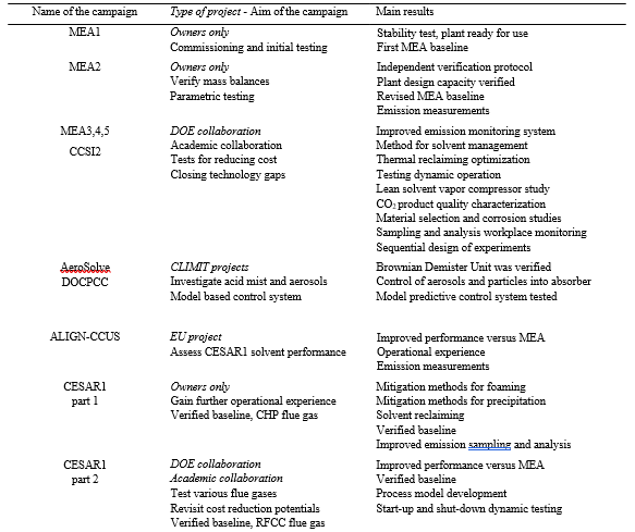
A summary of the open campaigns is given in Table 2. The MEA campaigns have been executed in several time periods and are designated MEA1, MEA2, MEA3, MEA4 and MEA5 to distinguish between the different tasks and projects that have been carried out. Similarly, the CESAR1 campaigns are designated CESAR1-part 1 and CESAR1- part 2.
Table 2. Summary of open campaigns.
By being as open as possible TCM has provided the CCS community many high-quality results that are reviewed multiple times. Many issues that used to be the sole domain of a few commercial vendors were published and provided benchmarks. The open campaigns also spurred new research, both at TCM and at other pilot and laboratories. The open campaign concept is planned to be continued. TCM’s next CESAR1 campaign may be part of the Horizon Europe Innovation Action funded project AURORA. Target applications are the refining, cement and materials recycling industries. This project is managed by SINTEF and will seek to optimize and qualify the solvent for commercial deployment [40].
6. Site for emerging technologies with lower technology maturity
The so-called site for emerging technologies (SET), where smaller post-combustion pilots can be tested was started in 2021. TCM’s owners pre-invested in access to both flue gasses, all utilities except steam, connection to the vent stack, paving and civil connection. This site allows testing next generation, less mature technologies such as membranes, adsorption or new solvents, while benefiting from the expertise of TCM on operations, maintenance, emissions etc. The site for emerging technologies enables to feed pilots with the two flue gas sources from the CHP (now MHP) and RFCC. It has so far attracted five test campaigns, all of them being part of DOE or EU funded projects. MTR and TDA completed the first two campaigns from June 2021 to March 2022. They demonstrated the scale- up the design and the performances of their technology. In 2023, SAIPEM and PROSPIN compared conventional absorber with rotating packed bed with an enzymatic accelerated carbonate solvent. Adsorbent based technologies developed through MOF4Air project and by Innosepra were also tested.
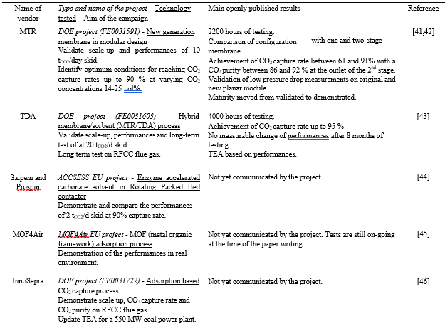
From these first test campaigns, vendors demonstrated the performances of their technologies in containerized design on real flue gas at scales ranging from 1 to 20 tCO2/day, with a focus on the CO2 capture rate, the CO2 product composition and long-term testing. These results are then generally used to update techno-economic assessments (TEA) and increase the maturity of the technology. For most of them, the change in scale provided them opportunities for improving the performance and reliability of their technology. In that sense, the SET can also be viewed, as a good training site to learn how to operate the units better, but also consider more robust design and select better pieces of equipment for the technology in its next upscaling phase. The Table below gives an overview.
Table 3. Campaigns at site for emerging technologies.
In conclusion, TCM’s SET provides a unique testing ground for less mature technologies where vendors can benefit from the expertise of TCM technical competence, which is very much derived from the operation of the amine plant. The plans for the future include a campaign by Svante to further validate its technology [47].
7. Knowledge sharing with advisory services and scientific papers
Knowledge sharing where possible has been an overarching aim of TCM. For this purpose, TCM has conducted the previously discussed open scientific campaigns, with non-proprietary solvents (MEA and CESAR-1) since 2013. These campaigns were conducted to address typical technical pitfalls observed in CCS projects. Since 2020, the results and experience from over 20,000 hours of non-proprietary solvent testing at TCM has been used to develop TCM’s Advisory Services as an additional tool for knowledge sharing.
TCM’s Advisory Services are facilitating the “translation” of the afore mentioned knowledge from the TCM scale to the industrial projects. Reports summarizing key learnings, tailor-made advisory projects and workshops are some of the ways that are serving as the vehicle that transfers knowledge. But the most convincing contribution to knowledge sharing are the nearly 70 scientific papers that have been published by TCM, research partners, technology vendors, and TCM owners [3], covering all aspects of the original ambitions. Not only the owners themselves have used them actively, but also the many in the CCS community.
8. Value to the owners and to the CCS industry
The above discussed achievements are the visible and documented results. But TCM’s owners are value oriented and see several other benefits. The 13 vendors who have been at TCM have created a diversity and competition in the market. Today, TCM’s owners and the CCS industry as a whole have a broader choice of vendors for their specific capture projects. All TCM’s vendors are active in the CO2 capture business, which includes R&D, engineering studies, licensing and construction. Next, the owners have first-hand access to high quality and reliable results, enabling them to evaluate technologies and projects. These results have shown to be a good basis for writing project specifications, procurement documents and negotiating guarantees on OPEX/CAPEX. In this context, the ownership of intellectual property remains with the vendor. Confidentiality is regulated through test agreements with each vendor. For owners who license their own CO2 capture technologies or have any other close relationship to a vendor ringfencing of intellectual property has been used as a tool to mitigate contamination. Finally, the industrial owners of TCM also pursue CO2 transport and storage projects. TCM’s contribution to the post-combustion field will benefit forthcoming projects within e.g. steel, cement and waste to energy sectors. And this may eventually result in increased volumes in the CO2 transport and storage market. For this aspect TCM’s learnings on CO2 product specifications has also been useful. TCM has shown to be very important in the Norwegian CCS project “Longship”, which is under construction. Both capture plants within this project, Heidelberg Materials cement factory in Brevik and Hafslund Oslo Celsio waste-to-energy plant at Klemetsrud have chosen independently vendors that have tested their technology at TCM. Moreover, the construction projects benefited from regular experience transfer.
9. What could be the opportunities and role of TCM for the future?
TCM has done and will continue to do campaigns to investigate and derisk most aspects of post-combustion capture related to energy demand, performances, solvent management, emissions, CO2 product purity and operational issues. Several new challenges have emerged, and new challenges will likely surface as the technologies are being deployed, to which TCM can contribute. Today, new post-combustion technologies like non-amine liquids, adsorbents, membranes, liquefaction, anti-sublimation are promising, but not proven. TCM is well equipped to test novel technologies other than conventional amines with the site for emerging technologies. Secondly, dispatchable and load following operation of power plants (covering the gaps that wind and solar leave behind) have become a more and more attractive business case. All in all, we can conclude that TCM has met its initial ambitions and is still delivering at the service of the whole CCS industry. From now, TCM is evolving in its business model. And there is a clear expectation that technology vendors and business projects take over gradually more of the financing, along with the commercial maturation of CCS.
10. Conclusions
This paper has reviewed the technology development done at Technology Centre Mongstad (TCM) from the perspective of the financing companies. Most of the initial ambitions are fulfilled since TCM has shown to have contributed actively to the development of CO2 capture technologies and market. First of all, the world’s largest test site for post-combustion CO2 capture technology was designed, built and started up. Next eight commercial technology vendors (seven amine based and one chilled ammonia based) have matured their technology in the large demonstration units, increasing the competition and diversity. Moreover, many open campaigns and derived advisory services have contributed to significant knowledge sharing. The nearly 70 scientific papers are the prime evidence. Finally, the site for emerging technologies has increased the diversity even more by allowing a larger variety and less mature technologies to be developed. Building on the already very useful results, there are still opportunities for continuing supporting CO2 capture deployment at TCM today. In conclusion, TCM is a successful public-private partnership on the development of a climate change mitigation technology.
Acknowledgements
TCM is currently financed by Gassnova (on behalf of Norwegian State), Equinor, Shell, TotalEnergies, technology vendors, research partners, EU, US DoE and Norwegian research programs.
References
1 De Koeijer G, Enge YO, Thebault C, Berg S, Lindland J, Overå SJ. European CO2 test centre Mongstad–Testing, verification and demonstration of post-combustion technologies. Energy Procedia 2009;1:1321-6. https://doi.org/10.1016/j.egypro.2009.01.173
2 TCM DA website on Transparency Act. https://tcmda.com/about-tcm#transparency_act- (accesssed September 2024)
3 TCM DA website with overview of publications. https://tcmda.com/publications/ (accessed September 2024)
4 Knudsen JN, Jensen JN, Vilhelmsen P, Biede O. First year operation experience with a 1 t/h CO2 absorption pilot plant at Esbjerg coal-fired power plant. Proceedings of European Congress of Chemical Engineering (ECCE-6) Copenhagen 2007
5 Lombardo G, Agarwal R, Askander J. Chilled Ammonia Process at Technology Center Mongstad – First Result, Energy Procedia. 2014;51: 31–9. https://doi.org/10.1016/j.egypro.2014.07.004
6 Baker Hughes website on Chilled Ammonia. https://www.bakerhughes.com/process-solutions/chilled-ammonia-process (accesssed September 2024)
7 De Koeijer G, Talstad VR, Nepstad S, Tønnessen D, Falk-Pedersen O, Mareee Y, Nielsen C. Health risk analysis for emissions to air from CO2 Technology Centre Mongstad. International Journal of Greenhouse Gas Control 2013;18:200-7. https://doi.org/10.1016/j.ijggc.2013.07.010
8 Gassnova website on HSE studies for health and environmental challenges. https://ccsnorway.com/hse-studies/ (accessed September 2024)
9 TCM DA website. https://tcmda.com/studies-with-focus-on-amine-components (accessed September 2024)
10 Gorset O, Knudsen JN, Bade OM, Askestad I. Results from testing of Aker Solutions advanced amine solvents at CO2 Technology Centre Mongstad, Energy Procedia 2014;63:6267–80. https://doi.org/10.1016/j.egypro.2014.11.658
11 Shell website, Shell to test carbon capture technology at Technology Centre Mongstad in Norway. https://www.shell.com/business- customers/catalysts-technologies/resources-library/trade-release-shell-to-test-carbon-capture-technology-at-techno.html (accessed September 2024)
12 IEA GHG website. Campbell M. Cansolv DC-201 Testing at TCM: Impact of degradation inhibitor on degradation rate and emissions. https://az659834.vo.msecnd.net/eventsairwesteuprod/production-ieaghg-public/1cbc121c4e694be5a2c922dfe1311cc0 (accessed September 2024)
13 Shell website. Behind Shell Technologies: CANSOLV CO2 Capture with Dr. Paul-Emmanuel Just and Karl Stephenne. https://www.shell.com/business-customers/catalysts-technologies/resources-library/behind-shell-technologies-cansolv-co2-capture-with- paul-emmanuel-just-and-karl-stephenne.html (accessed September 2024)
14 Bumb P, Patkar A, Mather R, Kumar R, Hall J, Morton F, Anthony J. Field Demonstration of Advanced CDRMax Solvent at the US-DOE’s National Carbon Capture Centre and the CO2 Technology Centre Mongstad DA, Norway, Energy Procedia 2017;114:1087-99. https://doi.org/10.1016/j.egypro.2017.03.1261
15 TCM DA website on ION. “TCM Is Unrivaled!”, https://tcmda.com/news/ion-tcm-is-unrivaled (accessed September 2024)
16 NETL DOE website on Fluor Solvent Testing at Technology Center Mongstad (Project 70814). https://netl.doe.gov/sites/default/files/netl- file/S-Readdy-PNNL-Solvent-Testing-at-TCM.pdf (accessed September 2024)
17 MHI website. Mitsubishi Heavy Industries Engineering Successfully Completes Testing of New “KS-21TM” Solvent for CO2 Capture. https://www.mhi.com/news/211019.html (accessed September 2024)
18 TCM DA website. RTI is testing at TCM: So far, so good! https://tcmda.com/news/rti-is-testing-at-tcm-so-far-so-good (accessed September 2024)
19 NETL DOE website. Project landing page. Engineering Scale Testing of Transformational Non-Aqueous Solvent-Based Carbon Dioxide Capture Process at Technology Centre Mongstad. https://netl.doe.gov/project-information?p=FE0031590 (accessed September 2024)
20 NETL DOE website. “Carbon Capture Solvent Technology To Be Tested at World’s Largest Test Facility”. https://netl.doe.gov/node/14238 (accessed October 2024)
21 Hamborg ES, Smith V, Cents T, Brigman N, Falk-Pedersen O, De Cazanove T, Chhaganlal M, Feste JK, Ullestad Ø, Ulvatn H, Gorset O, Askestad I, Gram LK, Fostås BF, Shah MI, Maxson A, Thimsen D. Results from MEA testing at the CO2 Technology Centre Mongstad. Part II: Verification of baseline results. Energy Procedia 2014;63:5994-6011. https://doi.org/10.1016/j.egypro.2014.11.634
22 Faramarzi L, Thimsen D, Hume S, Maxson A, Watson G, Pedersen S, Gjernes E, Fostås BF, Lombardo G, Cents T, Morken AK, Shah MI, de Cazenove T, Hamborg ES. Results from MEA testing at the CO2 Technology Centre Mongstad: Verification of baseline results in 2015, Energy Procedia. 2017;114:1128-45. https://doi.org/10.1016/j.egypro.2017.03.1271
23 Hume S, Shah MI, Lombardo G, de Cazenove T, Feste JK, Maxson A, Benquet C. Results from MEA Testing at the CO2 Technology Centre Mongstad. Verification of Residual Fluid Catalytic Cracker (RFCC) Baseline Results. Proceedings of the 15th Greenhouse Gas Control Technologies Conference 2021. http://dx.doi.org/10.2139/ssrn.3821037
24 Hume, SA, Shah MI, Lombardo G, Kleppe ER. Results from Cesar-1 Testing with Combined Heat and Power (CHP) Flue Gas at the CO2 Technology Centre Mongstad. 2021 Presented at Trondheim Conference on CO2 Capture, Transport and Storage https://hdl.handle.net/11250/2786512
25 Hume SA, McMaster B, Drageset A, Shah MI, Kleppe ER, Campbell M. Results from CESAR1 testing at the CO2 Technology Centre Mongstad. Verification of Residue Fluid Catalytic Cracker (RFCC) baseline results. 2022 Presented at the 16th Greenhouse Gas Control Technologies Conference, Lyon, France. http://dx.doi.org/10.2139/ssrn.4280571
26 Morken AK, Pedersen S, Nesse SO, Flø NE, Johnsen K, Feste JK, de Cazenove T, Faramarzi L, Vernstad K. CO2 capture with monoethanolamine: Solvent management and environmental impacts during long term operation at the Technology Centre Mongstad (TCM). International Journal of Greenhouse Gas Control, 2019;82:175-83. https://doi.org/10.1016/j.ijggc.2018.12.018
27 Gardarsdottir S, Faramarzi L, Jordal K, Campbell M. Critical Knowledge for CO2-Intensive Industries to Implement Amine-Based Carbon Capture. Proceedings of the 15th Greenhouse Gas Control Technologies Conference 2021. http://dx.doi.org/10.2139/ssrn.3813495
28 Johnsen K, Romslo KE, Faramarzi L, Benquet C, Gjernes E, De Koeijer G, de Cazenove T, Morken AK, Flø NE, Shah MI, Aronsson M, Ullestad Ø. CO2 Product Quality: Assessment of the Range and Level of Impurities in the CO2 product Stream from MEA Testing at Technology Centre Mongstad (TCM). 14th Greenhouse Gas Control Technologies Conference Melbourne 2018, https://ssrn.com/abstract=3365995
29 De Koeijer G, Benquet C, Knarvik ABN, Gjernes E, Pedersen S, Hvidsten OA, A Benchmark for Compact CO2 Capture Plant Designs by Monoethanolamine Solvent Testing at Technology Centre Mongstad, Proceedings of the 15th Greenhouse Gas Control Technologies Conference 2021. https://papers.ssrn.com/sol3/papers.cfm?abstract_id=3813201
30 Gjernes E, Pedersen S, Jain D, Åsen KI, Hvidsten OA, de Koeijer G, Faramarzi L, de Cazenove T. Documenting Modes of Operation with Cost Saving Potential at the Technology Centre Mongstad. 14th Greenhouse Gas Control Technologies Conference Melbourne 2018. https://ssrn.com/abstract=3366235
31 Shah MI, Silva E, Gjernes E, Åsen KI. Cost Reduction Study for MEA based CCGT Post-Combustion CO2 Capture at Technology Center Mongstad. Proceedings of the 15th Greenhouse Gas Control Technologies Conference 2021. http://dx.doi.org/10.2139/ssrn.3821061
32 Putta KR, Saldana D, Campbell M, Shah MI. Development of CO2 capture process cost baseline for 555 MWe NGCC power plant using standard MEA solution. Presented at the 16th Greenhouse Gas Control Technologies Conference 2022. http://dx.doi.org/10.2139/ssrn.4279671
33 Bui M, Mac Dowell N. Start-up and Shutdown Protocol for Natural Gas-fired Power Stations with CO2 Capture. 2022 IEAGHG Report IEA/CON/20/272. https://ieaghg.org/publications/start-up-and-shutdown-protocol-for-natural-gas-fired-power-stations-with-co2-capture/
34 Zhu L, Schade GW, Nielsen CJ. Real-Time Monitoring of Emissions from Monoethanolamine-Based Industrial Scale Carbon Capture Facilities, Environ. Sci. Technol. 2013;47:14306−14. https://doi.org/10.1021/es4035045
35 Morken AK, Nenseter B, Pedersen S, Chhaganlal M, Feste JK, Tyborgnes RB, Ullestad Ø, Ulvatn H, Zhu L, Mikoviny T, Wisthaler A, Cents T, Bade OM, Knudsen J, de Koeijer G, Falk-Pedersen O, Hamborg ES. Emission results of amine plant operations from MEA testing at the CO2 Technology Centre Mongstad, Energy Procedia 2014;63:6023–38. https://doi.org/10.1016/j.egypro.2014.11.636
36 Morken AK, Pedersen S, Kleppe ER, Wisthaler A, Vernstad K, Ullestad Ø, Flø NE, Faramarzi L, Hamborg ES. Degradation and Emission Results of Amine Plant Operations from MEA Testing at the CO2 Technology Centre Mongstad. Energy Procedia 2017;114:1245-62. https://doi.org/10.1016/j.egypro.2017.03.1379
37 Zhu L, Mikoviny T, Morken AK, Tan W, Wisthaler A. A compact and easy-to-use mass spectrometer for online monitoring of amines in the flue gas of a post-combustion carbon capture plant. International Journal of Greenhouse Gas Control 2018;78:349-53, https://doi.org/10.1016/j.ijggc.2018.09.003
38 Languille B, Drageset A, Mikoviny T, Zardin E, Benquet C, Ullestad Ø, Aronson M, Kleppe ER, Wisthaler A. Best practices for the measurement of 2-amino-2-methyl-1-propanol, piperazine and their degradation products in amine plant emissions. Proceedings of the 15th Greenhouse Gas Control Technologies Conference 2021. http://dx.doi.org/10.2139/ssrn.3812339
39 Drageset A, Ullestad Ø, Kleppe ER, McMaster B, Aronsson M, Olsen JA. Real-time monitoring of 2-amino-2-methylpropan-1-ol and piperazine emissions to air from TCM post combustion CO2 capture plant during treatment of RFCC flue gas. Presented at the 16th Greenhouse Gas Control Technologies Conference 2022. http://dx.doi.org/10.2139/ssrn.4276745
40 Aurora website, https://aurora-heu.eu/wp-content/uploads/2024/04/GHGT-17-CESAR1-degradation.pd (Accessed September 2024)
41 Batoon, V, Borsaly, A, Casillas, C, Hofmann, T, Huang, I, Kniep, J, Westling, E. Scale-Up Testing of Advanced Polaris™ Membrane CO2 Capture Technology. Proceedings of the 16th Greenhouse Gas Control Technologies Conference 2022. https://papers.ssrn.com/sol3/papers.cfm?abstract_id=4281208
42 Merkel, T, Salim, W, Casillas, C, Borsaly, A, Kniep, J, Westling, E, Sun, Z . Scale-up Testing of Advanced Polaris Membrane in CO2 Capture Technology. 2023 Technical report No. 383 U.S. Department of Energy Office of Scientific and Technical Information. https://www.osti.gov/biblio/1995006
43 Gribble, D, Hohman, J, Jayaraman, A, Hofmann, T, Kniep, J, Merkel, T, Alptekin, G. Demo-scale testing of a hybrid membrane-sorbent system for post-combustion CO2 capture. Proceedings of the 16th Greenhouse Gas Control Technologies Conference 2022. https://papers.ssrn.com/sol3/papers.cfm?abstract_id=4295185
44 M Montañés, R, Jordal, K, Schiesari, F, Anantharaman, R, Brunsvold, A, Mazzotti, M, Frieling, H. ACCSESS Project: Providing access to cost-efficient, replicable, safe and flexible CCUS. Proceedings of the 16th Greenhouse Gas Control Technologies Conference 2022. https://papers.ssrn.com/sol3/papers.cfm?abstract_id=4282876
45 Heymans, N, Duprez, ME, De Weireld, G. MOF4AIR project (H2020): Metal Organic Frameworks for carbon dioxide Adsorption processes in power production and energy Intensive industries. Proceedings of the 15th Greenhouse Gas Control Technologies Conference 2021. https://papers.ssrn.com/sol3/papers.cfm?abstract_id=3821559
46 Jais, R, Lemcoff, N. Transformational sorbent-based process for a substantial reduction in the cost of CO2 capture. Presentation at National Energy Technology Laboratory Carbon Management Project Review Meeting 2023. https://netl.doe.gov/sites/default/files/netl- file/23CM_PSCC30_Jain.pdf
47 TCM DA website. Svante to Test Groundbreaking Carbon Capture Filter Technology at TCM. https://tcmda.com/news/svante-to-test- groundbreaking-carbon-capture-filter-technology-at-tcm (accesse
CO2 Technology Centre Mongstad – Design, Functionality and Emissions of the Amine Plant (2011)
Gelein de Koeijer*a, Yngvil Engea, Knut Sandenb, Oscar Fr. Graffb, Olav Falk-Pedersenc, Tore Amundsenc, Sverre Overåa
a Statoil ASA, N-4035, Stavanger, Norway b Aker Clean Carbon N-0212, Oslo, Norway c TCM DA, NO-5954 Mongstad, Norway

Abstract

The CO2 Technology Centre Mongstad (TCM) project is constructing two large post-combustion CO2 capture demonstration plants near the Statoil operated Mongstad refinery, located at the Norwegian west coast north of Bergen. TCM’s partners are Gassnova, Statoil, Sasol and Norske Shell. This paper describes the amine plant. The amine plant is designed and constructed by the CO2 capture technology provider Aker Clean Carbon (ACC) with specifications and additional generic functionalities defined by TCM. Several new technology elements will be tested and verified, including improved solvents. Monoethanolamine and a new ACC solvent will be tested during the initial 16 months of operations. Thereafter tests will be run by the TCM partners. The quality and quantity of the emissions from the absorber to air have become top priority. Currently they represent a health and environmental uncertainty, mainly due to the lack of reliable and accessible experimental data. While knowledge and experience of these emissions are rapidly increasing, an emission permit is being applied for. The amine plant is highly flexible and can combine several novel technologies. Due to its scale it will give valuable information on utility and space requirements, scale-up properties and contribute to reducing HSE risks and costs.
1. Introduction
The CO2 Technology Centre Mongstad (TCM) project [1,2] is constructing two post-combustion CO2 capture test plants near the Statoil operated Mongstad refinery, situated at the Norwegian west coast north of Bergen. One unit will use amine technology and the other chilled ammonia technology. TCM’s partners are Gassnova (75,12% – representing the Norwegian State), Statoil (20%), Norske Shell (2.44%) and Sasol (2.44%). Statoil is the operator for the execution phase and has been selected as the operational service provider. The overall aims for TCM are:
- Test, verify and demonstrate CO2 capture technology owned and marketed by vendors
- Reduce cost, technical, environmental and financial risks
- Encourage the development of a market for such technology
- International deployment
At the moment of writing, this project is one of the largest CO2 capture demonstration units under construction. It is highly flexible in order to obtain information about different CO2 capture technologies. The amine plant is designed and constructed by the CO2 capture technology provider Aker Clean Carbon (ACC) [3]. The plant is under construction (see Figures 1, 2 and 3) and start-up is scheduled for 2011. The selected ACC’s Advanced Carbon Capture Process [4] includes several special new features such as:
- New improved amines, which exhibit less degradation and reduce energy demand
- Emission control system, which gives minimum emission to air
- Rectangular concrete absorber with internal liner
- Energy saver, which reduces the steam demand
- Two desorbers with alternative reboiler designs
- Thermal reclaimer design, which gives minimum waste
TCM will be a driving force in the qualification of large-scale capture technology and development of improved technology. The aim of this paper is to describe the design and functionality of the amine unit, and to contribute to the international deployment of TCM.
2. Method of design
The concept for the amine plant was defined through an industrial stage-wise development, which started summer 2007. International competition between technology suppliers was used. The criteria for the competition were based on fulfilling TCM’s aims. A pre-qualification process reduced the number of suppliers. After a bidding round based on Front End Engineering & Design (FEED) studies, Aker Clean Carbon (ACC) was chosen for the detailed design and construction early 2009. The basis for design is ACC’s amine based CO2 capture technology developed over the last years [3,4,5] but adapted to specifications, functionalities and flexibility requirements defined by the TCM project. Several new technology elements will be tested and verified in the plant, including improved solvents.
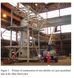
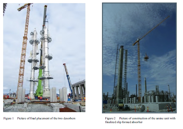
An important design strategy has been to utilize the same construction methods for the TCM plant as will be utilized for full scale plants. This can be exemplified by the absorber that has been slip formed, which is a great advantage for large constructions. Figure 2 shows the slip formed absorber at the Mongstad site. Another example is that the plant has been extensively modularized in order to prefabricate off-site. Figure 3 shows the construction of one of the reboilers on a pre-assembled unit at the Aker Stord yard, south of Bergen. This serves two main benefits; the productivity is generally greater at fabrication yards than site, and it is a risk reducing measure to minimize construction work close to complex sites as the Mongstad refinery.
3. Design and Functionality
3.1 Overall design
By fulfilling TCM’s aims specifically for the amine unit, the design has become one of the most advanced ones for amine plants with a high degree of flexibility. The process is an absorption/desorption process [3] and the overall design is shown by a 3D illustration in Figure 4.
The most important characteristic of the TCM facility is high flue gas flexibility by being able to capture CO2 from two different flue gas sources. This is a unique feature relative to other pilot and demonstration units of this size. The first flue gas is a slip stream from gas fired combined heat and power (CHP) flue gas with 3,5 vol-% CO2. This flue gas is representative of gas fired power plants. When using this flue gas the amine unit will have a capacity of 25 000 tonnes CO2/yr captured. The second flue gas is a slip stream from Residue Fluid Catalytic Cracker (RFCC) flue gas with 12,9 vol-% CO2.
This flue gas is representative of refineries, and also for coal fired power plants since it contains similar levels of SOx, NOx and particulates. When using this flue gas the amine unit will have a capacity of 74 000 tonnes CO2/yr captured. The unit is designed for 85% CO2 capture rate with CO2 purity of 99,9% for both CHP and RFCC flue gases. Furthermore, it will be possible to recycle captured CO2 to the CHP flue gas to achieve concentrations between 3,5 and 9% CO2 in the CHP flue gas. This will enable to test the effects of Exhaust Gas Recycle (EGR) [6] on amine based CO2 capture. The critical areas of interest for the technology include determining solvent degradation and process energy demand.
It will be possible to operate with large turn-downs. The design specification is 50% for both flue gasses which means a possible range of 16–100% for the CO2 product rate. Turn-down behaviour is especially important for quantifying load following capabilities and general flexibility. Relative to other capture technologies of pre-combustion and oxyfuel, this flexibility is said to be one of the important advantages of post-combustion [7]. The most interesting issues to be studied are the liquid distributor capacity and the vapour/liquid distributions in the packings.
Further, the flue gas treatment system upstream of the absorber allows for control and adjustment of flue gas temperature and water content. This allows the absorber inlet to be operated from 25 °C and up to more than 50 °C.
The utilities (steam and electricity) and tie-ins (ducts, blowers, flue gas coolers) are designed for 120% capacity to be able to test plant limitations. Normal design of CO2 capture units contains design margins. Currently these design margins have an uncertainty in the same range as the best available models. This uncertainty is estimated to be 10-20% [8]. Control of design margins is important for designing with minimum investment cost.
CO2 compression and storage is not included at this stage but may be added in a later phase.
3.2 Sampling, measurement and analysis
Being a demonstration unit where knowledge is the main product, extensive analyzers and monitoring instruments for measuring the improvements with high accuracy will be installed. The most important variables will be measured online where possible. The design includes many manual sampling points in order to be able to perform more detailed analyses. Special focus has been on emissions to air from the absorber (see Ch.4). It will be possible to fully define and where possible over-define the mass and energy balances in the unit in order to verify simulation models. In the absorber outlet and CO2 product temperature, pressure, flow, composition (CO2, N2, O2, Ar, H2O, NOx, SOx, amines, NH3, some degradation products) will be measured online. Corrosion coupons spool pieces are being installed to evaluate the use of other desorber, absorber, heat exchanger and piping construction materials than the ones used.
3.3 Solvents
The plant is designed to be able to test different solvents. ACC has scheduled to test the following:
- 30 wt% MEA (monoethanolamine) solution for 4 months, which is a well known solvent [9, 10]. The performance guarantees from ACC are based on this solvent. The results will give a benchmark for the novel solvents.
- improved solvent which contains mixtures of primary, secondary and tertiary amines developed by ACC and partners
The solvents will be tested both on RFCC and CHP flue gas. The improved solvent has demonstrated low degradation and reduced reboiler duty in tests at a coal-fired power station in Scotland (ref. section 3.6). A test program will be set up for obtaining best possible data, knowledge and experience.
3.4 Absorber
The absorber has a unique design and flexibility, see also Figure 5. The design philosophy from TCM was that it should enable testing of most amine based technologies. ACC has designed the absorber together with Koch-Glitsch as packing supplier. The CO2 absorption part has three packing sections for enabling 85% CO2 capture with slow and fast amines from RFCC, CHP flue gas and CO2-enriched CHP flue gas. The lowest section is the tallest one with two shorter sections above it of similar heights. Lean amine can be fed at the top of each section, but only above one section at a time.
The absorber design is part of ACC’s technology. The outer wall is rectangular (internal dimensions: 3,5x2x62 m) made of concrete with internal polymer lining. TCM will have the first lined concrete absorber in the world for CO2 capture from flue gasses with amines. The wall is slip formed with the liner continuously installed during the slip forming. The wall is penetrated extensively for various inlets, outlets, sampling points and online measurement instrumentation. The pressure drops will be measured over each packed section and the temperature will be measured every rising meter at a grid of horizontal locations. The outlet of the absorber is a conventional circular pipe (1 m diameter, 4 m height) with various penetrations for online Fourier transform infrared (FTIR) spectroscopy concentration measurement and iso-kinetic sampling. The flue gas inlet is designed with the aid of computational fluid dynamics to ensure proper gas distribution.
The wash section consists of water wash packings with demisters above and below. The water wash is designed such that ACC’s novel emission control system can be tested. There is a possibility of installing additional demisters. Relative to normal practice, this section may seem overdesigned. The reason is to quantify the emissions to air by experimenting with various washing configurations. This will contribute to reducing the residual health & environmental risk to an acceptable level.
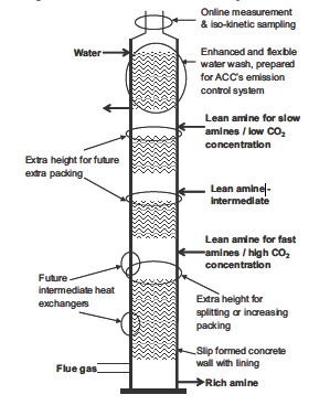
The division of CO2 absorption sections can be modified in the future. The lowest tallest section can be divided into two.the section improve the liquid/vapour distribution. Moreover, each of the 3 sections has a possibility of 10% increase in packing heights by adding extra height between liquid distributor and packing section.
By the addition of extra inlets, internal brackets and other provisions of extra distributors, it is also possible to add an intermediate heat exchanger at two different heights.
3.5 Desorbers and Reclaimer
TCM’s amine unit has two strippers or desorbers, enabling operation with minimum energy demand with both flue gases. Moreover two desorbers are needed to meet the turn-down requirements. ACC has designed the desorbers using Koch-Glitsch as packing supplier. The diameter of the RFCC desorber is 2,2 m and for the CHP desorber 1,2 m. Both desorbers have one packed section for CO2 desorption and one for water wash above the rich amine inlet. Height is reserved and penetrations are made for the possibility to split the CO2 desorption section for future installation of split flow and/or better vapour/liquid distribution. The pressure in the desorbers can be increased and reduced. Pressure variation tests can reveal the optimum compromise between steam demand, steam quality, compressor requirement and degradation for each solvent and flue gas.
Each desorber has its own reboiler which is designed for current scheduled operation. Each desorber can be fitted with a second reboiler in case another type of operation is decided, or new or optimized types of reboilers are developed.
The RFCC desorber has installed ACC’s technology for recovering energy in pressurized hot lean amine [3]. The CHP desorber does not have such an Energy Saver, but provisions are made for future installation. The Energy Saver converts low value energy into useful stripping energy and includes heat integration. This Energy Saver requires more electricity but less steam, and leads overall to reduced energy demand.
The reclaimer will be a thermal reclaimer with external steam heating. It will be used initially for getting data and experience, which is scarce for reclaiming. It is possible to upgrade the current reclaimer for reduced pressures. Valves are installed and place is reserved for a future 2nd reclaimer with improved technology.
3.6 Mobile test unit
In the initial period of operations, ACC’s Mobile Test Unit (MTU) will be installed at the Mongstad site, and will be used for tests in parallel to the larger unit. It has an absorber diameter of 0,4 m, a height of 25 m, and a capture capacity of 0,2 t CO2/hr on flue gas from coal fired power plants. It has been operated in Risavika Gas Centre (Norway) on flue gas from a gas turbine and in Longannet (Scotland) on flue gas from a coal fired power plant as part of the SOLVit R&D project [5]. It will be used to gain early test results and experience from operation on two different flue gas sources with new amines. However, such tests lack the large-scale effects and some of the flexibility of the larger scale unit. The combination of results from both units will be synergetic.
4. Emissions to Air
The quality and quantity of the emissions to air have become top priority. Currently they represent a health and environmental uncertainty, mainly due to the lack of reliable and accessible experimental data. A new emission control system will be tested in the TCM amine absorber. The system has the potential to reduce the emission of amines and degradation products to a minimum. A large part of the efforts in this project went into assessing the assumptions on the formation, dispersion and acceptance criteria of carcinogenic nitrosamines. Nitrosamines are assumed to be formed from reactions between secondary/tertiary amines and NOx, both in the absorber and in the atmosphere. There are several, major uncertainties in the selected nitrosamine assumptions, such as formation time and conditions, stability, and resulting concentration levels in the plant and surroundings. Formation of nitrosamines has been experimentally observed in laboratory experiments [10]. New knowledge is being rapidly generated and various experiments are being executed [10, 11, 12, 13]. In this continuously changing situation, TCM is applying for an emission permit to the Norwegian authorities in the summer of 2010 [13]. This application is the world’s first application for a larger scale amine unit that addresses the emissions in detail, and can be considered as pioneering work. In short, the procedure of writing this permit consisted of obtaining:
- The best possible estimates of the emissions from ACC, i.e. an environmental budget. Qualitative measurements, analogies and theory were used for estimating the emissions. The estimates were given in the form of scenarios in order to capture the whole range of operations, including high values during upsets and low values which are expected from theoretical calculations. As an example, the estimates for two scenarios (expected and design) for MEA for CHP and RFCC flue gasses are given in Table 1 for three of the main emitted components. The expected values are the most likely ones normal operation will be below. The design values are those used for the design described earlier in this paper. As can be seen in the Table, the design values are already conservative relative to the expected values. The estimates are based from measurements at the MTU. Other components that have been observed in the measurements from the MTU are formaldehyde, methylamine, ethylamine, dimethylamine, formic acid, acetic acid, butyric acid, propionic acid, n-(2-hydroxyethyl)imidazole, n-(2- hydroxyethyl)-formamide and nitrosamines as a group. In addition, it is likely that ketones, amides and other secondary amines will be present.
| Expected (ppmv) | Design (ppmv) | |||
| CHP | RFCC | CHP | RFCC | |
| MEA | 0.5 | 0.5 | 1 | 1 |
| NH3 | 2.6 | 16.5 | 5.1 | 33 |
| Acetaldehyde | 1.3 | 0.825 | 2.55 | 1.65 |
Table 1 Estimate of 3 concentrations of emissions from absorber in the expected and design scenarios for CHP and RFCC flue gasses using MEA.
- Health, safety and environmental data on all amines and their degradation products, i.e. biodegradability, ecotoxicity, acute toxicity, mutagenicity, reproduction toxicity, irritation/corrosion, sensitation, repeated dose toxicity. ACC used SINTEF as consultant for this work, including searching the International Uniform ChemicaL Information Database (IUCLID), the ECOTOX database of the US Environmental Protection Agency (EPA), the BIODEG database of the Syracuse Research Centre (SRC), and the GENETOX database (EPA). Data for all components need to be collected, even if the amine or its degradation product is non-volatile giving negligible emissions. Operators can still come into contact with it during operations like reclaiming, filter change, sampling etc.
- Acceptance criteria and exposure limits for all amines and their degradation products in air and drinking water by searching
Norwegian and international HSE regulations and using the new REACH regulation from the European Union.
- Dispersion modelling results for all amines and their degradation products in air and drinking water. This work was done by Norwegian Institute for Air Research (NILU) and used input from all previous activities.
Due to the mentioned uncertainty the precautionary and worst case principles have been used actively, which has lead to the use of several assumptions. An important assumption is on how much of the emitted amine reacts with NOx in the atmosphere to nitrosamines. It is assumed that 2-10% of all emitted secondary and tertiary amines are transformed instantaneously into nitrosamines [13]. It is further assumed that the formed nitrosamines are 100% stable in the atmosphere and will not decrease. This is a precautionary approach which is recommended at this stage. R&D on this assumption has started [13] but there is still little published experimental and theoretical evidence. As yet, Norway does not have acceptance criteria for nitrosamines in air and drinking water. Hence, information from outside Norway had to be assessed. It was decided to use the criteria from the nitrosamine with the lowest concentrations found in EPA/IRIS for all nitrosamines, i.e. a group approach. These were found for N-nitrosodimethylamine, and are 0.07 ng/m3 for air 0.7 ng/l for drinking water [14].
After the data gathering and modelling an application was written for certain emission rates that satisfy the acceptance criteria. Such rates are meant to give flexibility for performing the desirable tests. Hence, they are not actually measured rates but aggregated numbers with contingencies. It is expected that new knowledge will elucidate the validity and level of conservatism of the numbers and assumptions in the application. However, they are considered to be the most valid ones with current available knowledge. For other future applications of these assumptions it is recommend to critically re-assess them with the most recent knowledge.
5. Technology Qualification
A structured technology qualification program is being executed for reducing the technology risks to an acceptable level for such a demonstration unit. The work consisted of making a qualification basis, technology assessment, failure mode identification and risk ranking, and selection of qualification methods. The technology qualification program has been designed by ACC with DNV as consultant, and has followed a specific procedure for CO2 capture presented in earlier published work by DNV [15]. These guidelines were developed in an R&D Joint Industry Project (with Aker Solutions, Aker Clean Carbon, Statoil, Statkraft, and DNV as partners). They are now used in an industrial environment for the first time. The detailed results are an important part of ACC’s competitive knowledge. The main technology risks were related to the emissions to air and absorber construction and functionality. Hence, the ongoing execution of the qualification methods is mainly focused on reducing these risks. A good example is the construction of a mock-up of the slip forming platform for the absorber, see Figure 6. With this mock-up the slip forming technology was tested before it was used in spring 2010 for the actual absorber.
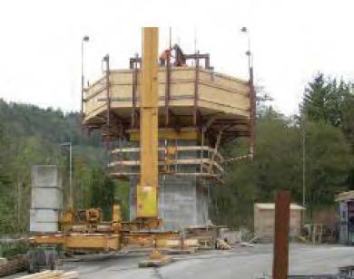
This mock-up has contributed to the 62 m high concrete absorber being successfully raised within 20 days by the tested slip forming method.
6. Conclusions
An amine demonstration unit is being constructed at the CO2 Technology Centre Mongstad, located north of the city of Bergen in Norway. At the moment of writing, this unit will be one of the largest demonstration units for experimenting with amine technology. The design is highly flexible with an absorber with multiple sections and two desorbers with different diameters. Ample provisions for future improvements are also included. The unit can capture flue gasses representative of gas and coal fired power plants, as well as petrochemical plants and refineries. The technology supplier is Aker Clean Carbon and several new design features will be tested. Due to its scale it will give valuable information on utility and space requirements, scale-up properties and contribute to reducing HSE risks and costs. 30 wt% MEA and a new solvent developed by ACC and partners will be tested during the initial 16 months of operations. Subsequent testing will be done by the TCM partners. Construction technologies that may reduce construction cost of large scale units are also included. In parallel a much smaller Mobile Test Unit will be used for faster and cheaper tests that can benefit the test at the larger unit.
The quality and quantity of the emissions to air have become top priority. Currently they represent a health and environmental uncertainty, mainly due to the lack of reliable and accessible experimental data. New knowledge is being rapidly generated and various experiments are being executed. In this continuously changing situation, TCM is applying for an emission permit to the Norwegian authorities. It is expected that new knowledge will elucidate the validity and level of conservatism of the numbers and assumptions in the application. However, they are considered to be the most valid ones with current available knowledge.
Another novelty in this project is the use of recently developed guidelines for technology qualification of CO2 capture technology.
7. References
- De Koeijer GM, Enge YO, Thebault C, Berg S, Lindland J, Overå SJ. European CO2 Test Centre Mongstad –Testing, verification and demonstration of post-combustion technologies, Energy Procedia 2009;1:1321-1326
- Website on CO2 Technology Centre Mongstad www.tcmda.com (accessed July 2010)
- Aker Clean Carbon website, www.akercleancarbon.com (accessed July 2010)
- Oscar Fr. Graff, European CO2 Technology Centre Mongstad – Advanced Amine Carbon Capture Plant, Trondheim CCS-5 international conference 2009, http://www.energy.sintef.no/arr/CO2_2009/Presentations/B3-3.pdf (accessed July 2010)
- Website on SOLVit program, http://www.akercleancarbon.com/section.cfm?path=418,465 (accessed July 2010)
- ElKady AM, Evulet A, Brand A, Ursin TP, Lynghjem A. Application of Exhaust Gas Recirculation in a DLN F-Class Combustion System for Postcombustion Carbon Capture. J. Eng. Gas Turbines Power 2009;131;3:034505-[7]
- Lucquiaud M, Chalmers H, Gibbins J. Capture-ready supercritical coal-fired power plants and flexible post-combustion CO2 capture, Energy Procedia, 2009;1:1411-1418
- Luo X, Knudsen JN, De Montigny D, Sanpasertparnich T, Idem R, Gelowitz D, Notz R, Hoch S, Hasse H, Lemaire E, Alix P, Tobiesen FA, Juliussen O, Köpcke M, Svendsen HF. Comparison and validation of simulation codes against sixteen sets of data from four different pilot plants. Energy Procedia, 2009;1:1249-1256
- Knudsen JN, Jensen JN, Vilhelmsen PJ, Biede O, Experience with CO2 capture from coal flue gas in pilot-scale: Testing of different amine solvents, Energy Procedia, 2009:1;783-790
- Fostås B, Sjøvoll M, Gangstad A, Nenseter B, Pedersen S, Sørensen AL, The flue gas degradation chemistry of MEA based solvents, Submitted to Proceedings of GHGT-10 Amsterdam Sept 2010
- Lepaumier H, Da Silva EF, Einbu A, Grimstvedt A, Knudsen JN, Zahlsen K, Svendsen HF, Comparison of MEA degradation in pilot-scale with lab-scale experiments. Submitted to Proceedings of GHGT-10 Amsterdam Sept 2010
- Website for R&D project “Atmospheric Degradation of Amines” – ADA http://ada.nilu.no/ (accessed July 2010)
- TCM. Application for emission permit with appendices, to be published on www.klif.no (Norwegian) 2010
- EPA/IRIS database entry for N-Nitrosodimethylamine, http://www.epa.gov/ncea/iris/subst/0045.htm (accessed July 2010)
- Myhrvold T, Helle K, Johnsen K, Hussain A. Development of a guideline for the qualification of CO2 capture technology, Energy Procedia 2009;1:1527-1534
European CO2 Test Centre Mongstad - Testing, Verification and Demonstration of Post- Combustion Technologies (2009)
Gelein de Koeijer*b, Yngvil Oftebro Engeb, Cyril Thebault c, Svein Bergb, Julia Lindlanda, Sverre Johannesen Overåb
aGassnova SF, N -3920 Porsgrunn, Norway
bStatoilHydro ASA, N-4035, Stavanger, Norway
cVattenfall AB, SE-162 87 Stockholm, Sweden

© 2008 Elsevier Ltd. Open access under CC BY-NC-ND license.
Abstract
The European CO 2 Test Centre Mongstad project will construct two post-combustion CO2 capture test plants (amine and chilled ammonia) with total annual CO2 capacity of 100,000 tones. The ambitions are:
- Develop technologies for CO2 capture capable of wide national and international deployment
- Reduce cost and technical, envi ronmental and financial risks related to large scale CO2 capture
- Test, verify and demonstrate CO2 capture technology owned and marketed by vendors
- Encourage the development of a market for such technology
Both plants will be able to capture CO2 from two d ifferent flue gases with 3.5 and 12.9 mol% CO2.
1. Introduction
On 12 th October 2006 Statoil (now StatoilHydro) and the Norwegian State agreed on implementation of CO2 Capture and Storage (CCS) at the Mongstad refinery [1]. The Mongstad refinery is located north of the city Bergen in Norway. T he refinery is operated by StatoilHydro. In 2010 major improvements of the refinery will be ready including connections to several of its neighboring industrial sites and offshore platforms. This improvement includes the construction of a Combined Heat and P ower plant (CHP) which will add ~1.3 million tonnes CO2 per year to the emissions to the already existing emissions from the refinery, of which t he Residue Catalytic Cracker (RCC) is the largest contributor with ~0.8 million to nes CO2 per year. The agreement requires a two-stage implementation of CCS. The first stage is the European CO2 Test Centre Mongstad (TCM) with a design capacity of 100 000 tonnes of CO2 /year. The second stage is full scale implementation. The aim of this paper is to describe the tech nical choices and aims of the first stage – TCM.
The purpose of the test centre is to identify, test, develop and qualify CO2 capture technologies, and to reduce cost and financial, technical and environmental risk connected to the construction and operati on of a full scale CO2 capture plant. The ambitions of the TCM project are:
- Develop technologies for CO2 capture capable of wide national and international deployment
- Reduce cost and technical, environmental and financial risks related to large scale CO2 capture
- Test, verify and demonstrate CO2 capture te chnology owned and marketed by vendors
- Encourage the development of a market for such technology
The TCM partners are Gassnova SF (representing the Norwegian State), DONG Energy, Shell, StatoilHydro, and Vattenfall. The partners are operators from both oil&gas and power industry, and participate actively in the developmentof CO2 Capture and Storage.
2. Technology Assessment
Many technologies for CO2 capture are documented [2], and groups of these technologies have previously been assessed on various bases , see e.g . Steeneveldt et al [3] and CO2 Capture Project (CCP) [ 5]. At the start of the TCM project these technologies needed to be assessed with TCM specific demands enabling a technology choice. T he following criteri a were used together with the knowledge from the partners:
- Extent of modification and disturbances to the CHP and refinery. The operation of TCM (and the later full scale capture plant ) should not require any modifications to the CHP plant and refinery, nor disturb their operations
- Usefulness and improvement potential for the large-scale Mongstad CO2 capture plant
- General improvement potential relative to MEA based post -combustion (as documented by e.g. IEA [ 4] and CCP [ 5])
- Availability of established and emerging suppliers for the TCM project
- Technology demonstration and qualification aims of TCM in relat ion to its maturity. TCM should preferably demonstrate and qualify new and most probably immature technology.
- CO2 capture plant at Mongstad will have no harmful emissions in accordance to the zero harmful emission target of the Norwegian authorities and the Mongstad emission permit
- The possibility to capture CO2 fromthe high CO2 content flue gas from the RCC addition to CHP
The result was to recommend improved amine and c hilled ammonia technology. Amine technology is w ell known, simple and flexible, but still has improvement potential on steam demand, cost, emissions, discharges, solvent formulations, materials/ corrosion, and scale-up. An important reference was the Esbjerg pilot unit [6], which is the largest amine based post -combustion pilot unit in the world with a 1 to n CO2 per capacity and 1 m diameter absorber. The chilled ammonia technology uses the general absorption/desorption based on a carbonate/bicarbonat e cycle :
CO2(g) + CO32-(aq/s) + H2O (l) Û 2HCO3– (aq/s)
The reaction needs a cation for which the supplier Alstom has chosen ammonium. Alstom is developing this technology and calls it the ‘Chilled Ammonia Process’ (CAP) [7]. Its possible advantages are reduced energy demand, fewer CO2 compressor stages, well known low cost chemicals, and reduced amount of waste . However this technology is unproven, has few available experimental data, need s extensive cooling, and requires handling of slurries and ammoni a. The chilled ammonia technology h as been tested less and therefore represents a higher risk.
3. Overall Concept and Functional Requirements
Figure 1 shows the TCM overall concept and design capa cities based on the main functional requirements agreed in the early phase of the project. Each of t he two CO2 capture technologies (Amine / C hilled Ammo ni a) shall be able to capture CO2 from two different flue gas sources (CHP/RCC) and shall operate independent of each other . The CHP flue gas represents a gas fired power plant with 3.5 mol% and the RCC flue gas represents coal fired power plant with 12.9 mol% with particulates, SOx and NOx.
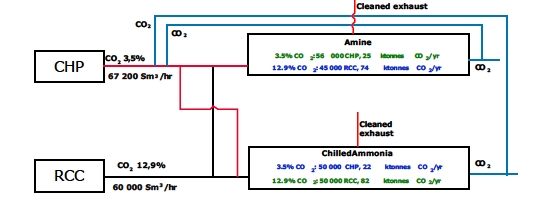
The design capacity will be 100 000 t ones CO2/yr if both technologies operate simultaneously with > 85% CO2 capture efficiency and 92% regularity. It will be possibl e to simulate the effects on CO2 capture of gas turbine Exhaust Gas Recycling (EGR ) by CO2 recycle from either plant back to the CHP flue gas . EGR is a technology for increasing the CO2 concentration to ~4-8 mol% and reduce the flue gas volume from gas fired turbines, see e.g. CCP [5]. The technologies need to have high flue gas flexibility in each CO2 capture unit for handling both CHP and RCC flue gas. The plants will be designed such that scale-up to full-scale plant can be done based on the results from TCM. The amine technology has different gas flows through the absorber for RCC and CHP exhaust, while carbonate has the same. The reason was that the carbonate absorber performance was estimated to be less sensitive for CO2 concentration than amine. The maximum flue gas flows from the sources are 20-34% too large relative to what is estimated needed in the capture process. This will give flexibility and the ability to test the limits. Their sizes ar e chosen by a compromise between this flexibility and duct/tie-in cost.
Further, since the ambition for TCM is to create a centre for testing of post -combustion CO2 capture technologies and associated facilities, the TCM project includes access to flue gas es, utilities and captured CO2, as well as additional space reserved for testing of new (future) equipment and technologies in smaller or similar scale as the initial two technologies. CO2 compression and storage is not included at this stage but may be added in a later phase. The sizes of these plants will be significantly larger than the existing pilot plants. The absorber diameters will be expected to be around 2.5 -4.0m, while their heights may be 40-60m. Relative to the Esbjerg unit a scale-up factor of 5-10 will reached. It is expected that this size increase will be an important contribution in the scale -up of post-combustion CO2 capture.
4. Test objectives
The overall test objectives are:
- Demonstrate/quali fy and scale-up of high risk technologies (Chilled ammonia)
- Achieve incremental technology improvem ents in a generic and flexible a mine test unit
- Build and share knowledge and competence of CO2 capture technology among th e partners for full -scale realization
- Construct a test plant for CO2 capture tech nology applicable for both gas- and coal-fired power stations, balancing and taking into account the needs (application, geography) of the individual partners
- Measure and compare test results against reference cases to achieve the strategic ambitions
- Obtain good relations to vendors of CO2 capture technology and understand their offerings and capabilities
5. Design of Amine Plant
This chapter describes the main specific test objectives and functionality requirements for the amine plant.
HSE: Main HSE issues identified are the emissions and discharges of the solvents used , i.e. main amines, degradation products, activators, inhibitors, anti -foams, metals/metaloxides, SO x, and NOx. Technology and equipment that avoid these emissio ns will be included as far as reasonably possible for a test plant. Sampling, measurement and analysis methods and tools will be documented and tested for use before the start-up. U se and production of environmentally harmful chemicals need to be minimized during design.
Equipment: The pl ant will consist of one flexible absorber and two strippers for enabling CO2 capture from both RCC and CHP gas. One stripper will be designed for CHP exhaust and one for the RCC exhaust. Moreover, it will be used for testing of different solvents, requiring a high flexibility of operating parameters and filling/emptying capabilities. Verification of reduced h eat and electricity demand is of high priority. In order to have flexibility in future improvements, s pace will be allocated for:
- Inter-stage abso rber cooling
- Split flow from both strippers
- Additional reclaimer
- Additional reboilers in both strippers
- First stage of CO2 compression train
Nozzles and space have been allocated to allow testing of new or alternative equipment components within the initial plant.
The plant will allow for accurate measurement of temperatures, pressures, flows and composition. Mat erials testing test facilities for other steel qualities, concrete, coated mater ials and plastic will be installed . Multiple temperature and pressure measurement devices in absorber and stripper will be installed. Measurement of the amine and other chemicals in the entrained washing water will be possible. It shall be possible to measure the impact of SO2, NOx, particles, iron oxides and chlorides on the amine plant performance (e.g. amine degradation rate, filtration rate, corrosion rate, etc.)
Absorber : The absorber will have at least three sections of packing for CO2 removal complete with liquid distributors and liquid draw trays:
- The height of t he lowest bed is determined by the performance of a fast amine with RCC flue gas
- The second height is determined by the performance of a fast amine with CHP flue gas and of a slow amine with RCC flue gas. In case these heights significantly differ a fourth section can be included
- The third height is determined by the performance of a slow amine with CHP flue gas.
It will be possible to replace the packing/packing material with other packing type and other packing materials,
i.e. structured, random and plast ic. Below a demister, two water wash sections will be installed in the top of the absorber with minimum water consumption as design criterion. Space for a second demister will be allowed for.
Strippers : The two strippers will have at least two sections o f packings with nozzles and brackets to enable installation of liquid distributors and liquid draw trays for split flow operation. It will be possible to take out packing. The energy contained in the pressurized hot lean amine leaving the RCC -stripper will be utilized for reducing overall energy demand of the plant when capturing CO2 from the RCC gas. It will be possible to run the RCC-stripper without this technology.
Testing ranges: It will be possible to operate with CO2 concentrations in flue gas from 3.5 -12.9 mol% with minimum steam conditions at 100% load and 50% turndown for qualification for large-scale operation by utilizing the flexibility provided by multiple absorber sections and two strippers. Testing of RCC flue gas will be possible at varying of SO2 conc entrations. It is aimed to have a long term test at stable high SO2 concentrations. It will be possible to test different solvents.
An extensive test and development program will be prep ared utilizing the available functionalities before start-up.
6. Design of Chilled Ammonia Plant
The Chilled Ammonia Process (CAP) is currently being developed and commercialized by Alstom. The technology is ne w and the first pilot plant with continuou s operation of integrated absorber and regenerator was started 2008 at WE Energies coal fired power plant in Wisconsin , USA [8 ]. Figure 2 shows a 3D sketch of the CAP at TCM as envisaged by Alstom.
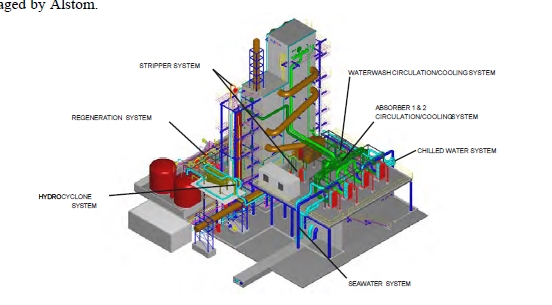
Chemistry and heat integration in the CAP are more complex compared to other commercially available CO2 capture technologies. There will be precipitation of ammonium bicarbonate, e.g. a mixture of solid particles of bicarbonate and the liquid solvent will form a slurry. Solids have thus to be handled during process operation. However, amm onium bicarbonate will dissolve during heating of the solvent in the lean/rich heat exchanger and in the regenerator, which operates at high pressure. Ammonia in water is volatile, and special measures h ave to be taken to avoid excessive emissions of ammonia to the environment. Emissions to air and to discharges to sea need to be l imited and the ammonia loss need to be kept at a minimum.
With respect to HSE, design data and testing ranges, the Chilled Am monia plant will be subject to many of the same design and functionality items as mentioned for the amine plant. Multiple temperature and pressure measurements in absorber and stripper will be provided to enable establishment of complete mass and energy balances. The design will also allow for liquid, gas and solid sampling and pH measurement at feed, exit and intermediate points in the absorber and stripper. The design shall allow for the simulation of the non optimal conditions (off set conditions).
The test program for Chilled Ammonia will focus on the following:
- Determination of the ammonia losses from test plant.
- Evaluation of the stripper operating pressure.
- Evaluation of process temperatures on thermal duty and CO2 capture efficiency
- Assessment of process kinetics for selected operating conditions
- Evaluation of performance of equipment
- Long duration tests of stable operation at industrial conditions.
- Evaluation of sensitivities to flue gas composition (sulphur, oxygen, particles, etc.) .
- Determinatio n of material and corrosion issues.
- Confirmation of operational stability and robustness.
- Evaluation of c hallenges around slurry operation and influence of solids content. In particular, turn down o peration, process control and operation, fouling and transportability, solid separation.
- Assessment of foaming issues for process.
- Determination of NH3/CO2 in rich and lean solvent all ove r the process and evaluate its impact on CO2 capture efficiency and steam consumption.
The activities on the chilled ammonia will progress in parallel with those of the amine plant . Determi nation o f design philosophy, in p articular with respect to scale -up is an important activity before start -up, and will be verified in the test program.
7. Time Scedule
The investment decision and project approval is planned for end of 2008. It is aimed to have the start -up in 2011. The first test campaigns will start after about some months of comissioning. TCM will be operated for a period o f at least 5 years enabling an extensive validation and development o f the chosen technologi es. More information on future developments can be found on the TCM homepage on the website of Gassnova SF [ 9].
8. Conclusions
The European CO2 Test Centre Mongstad will be a n important d riving force in the qualification of large -scale capture technology and development of improved technology. It will establish an international test site for emerging technologies, equipment and solvents, as well as a location suitable for a wide range of research related to CO2 capture technology. It will contribute in the search for ways to reduce the CO2 emissions and to limit the environmental consequences of human activities. This project is unique in the world due to its ambitions, its flexibility of CO2 so urces and technologies, its cooperation of international companies from both oil and power industry and its agreement that initiated the project. We will be “catching our future”!
9. Acknowledgements
The authors thank the TCM steering committee and the partners Gassnova SF (representing Norwegian State), DONG Energy, Shell, StatoilHydro, and Vattenfall for granting permission to publish this paper. The authors would like to express their gratitude to all current and previous TCM team members.
10. References
- Website of Norwegian Government (Norwegian only) , http://www.regjeringen.no/upload/kilde/oed/prm/2006/0143/d dd/pdfv/293147- avtale_mellom_staten_og_statoil_mongstad _12_okt_06.pdf, October 2006
- Intergovernmental Panel on Climate Change (IPCC), Carbon Dioxide Capture and Storage, IPCC Special Reports, http://www.ipcc.ch/ipccreports/srccs.htm , ISBN-13 978-0 -521 -86643-9, Cambridge University Press, New York, USA , 2005
- R. Steeneveldt, B. Berger and T.A. Torp, Chemical Engineering Research and Design , 84-9 (2006) 739
- IEA Greenhouse Gas R&D Program, Improvement in Powe rG eneration with Post -Combustion Capture of CO2, Report Number PH4/33 , 2004
- D. C. Thomas (Ed.), Carbon Dioxide Capture for Storage in Deep geological Formations – Results from the CO2 Capture Project, ISBN 0 -08 -044570-5 (2 volume set), Elsevier, Oxford, UK , 2 005
- J.N. Knudsen, J. N. Jense n, P. Vilhelmsen and O. Biede, First year operation experience with a 1 t/h CO 2 absorption pilot plant at Esbjerg coal -fired power plant , Proceedings of European Congress of Chemical Engineering (ECCE-6 ), Copenhagen, 16 -20 September 2007.
- N. Solie, Chilled Ammonia Process for Post-Combustion CO2 Capture, Tekna kursdagene , NTNU, Trondheim, 3 -4 January 2008
- Press release by Reuters, http://www.reuters.com/articl e/pressRelease/idUS225 300+27 -Feb- 2008+BW20080227, Feb. 27, 2008
- Gassnova TCM homepage , http://www.gassnova.no/, 2008