
3. Results from MEA amine plant corrosion processes at the CO2 Technology Centre Mongstad (2016)
Silje Hjelmaasa,b, Erlend Storheima,b, Nina Enaasen Fløa, Eva Svela Thorjussenb, Anne Kolstad Morkena,b, Leila Faramarzia,b, Thomas de Cazenovea, Espen Steinseth Hamborga,b,*
aCO2 Technology Centre Mongstad (TCM DA), 5954 Mongstad, Norway bStatoil ASA, PO Box 8500, 4035 Stavanger, Norway *Corresponding author
(http://creativecommons.org/licenses/by-nc-nd/4.0/).
Peer-review under responsibility of the organizing committee of GHGT-13.
doi: 10.1016/j.egypro.2017.03.1280
Abstract
In 2015, the CO2 Technology Center Mongstad (TCM DA), operated a test campaign using aqueous monoethanolamine (MEA) solvent at 30 wt%. The main objective was to demonstrate and document the performance of the TCM DA Amine Plant located in Mongstad, Norway. During the test period TCM DA monitored severa l indicators for corrosion, as well as analyzed corrosion coupons exposed to rich and lean solvent during the campaign. The results indicate unacceptable levels of corrosion for S235, coarse general corrosion for Inconel 600, and acceptable levels of corrosion for SS304L, SS316L , 22 Cr duplex SS, Stellite 6, Stellite 12 and EPDM. Some pitting was however observed on 316L stainless steel. No stress corrosion cracking was found on SS304L and SS316L.
1. Introduction
The CO2 Technology Centre Mongstad (TCM DA) is located next to the Statoil refinery in Mongstad, Norway. TCM DA is a joint venture set up by Gassnova representing the Norwegian state, Statoil, Shell, and Sasol. The facility run by TCM DA entered the operational phase in August 2012 and it is one of the largest post -combustion CO2 capture test centres in the world. A unique aspect of the facility is that either a flue gas slipstream from a natural gas turbine based combined heat and power (CHP) plant or an equivalent volumetric flow from a residual fluidized catalytic cracker (RFCC) unit can be used for CO2 capture. The CHP flue gas contains about 3.5% CO2 and the RFCC flue gas contains about 13-14% CO2. One of the main test plants at TCM DA is a highly flexible and well-instrumented amine plant. The amine plant was designed and constructed by Aker Solutions and Kværner to accommodate a variety of technologies, with capabilities of treating flue gas streams of up to 60,000 standard cubic meters per hour. The plant is being offered to vendors of solvent based CO2 capture technologies to, among others, test; (1) the performance of their solvent technology, and (2) technologies aimed to reduce the atmospheric emissions and environmental impact of amines and amine based degradation products from such solvent based CO2 capture processes. The objective of TCM DA is to test, verify, and demonstrate CO2 capture technologies suitable for deployment at full-scale. Up to now the vendors Aker Solutions, Alstom, Cansolv Technologies Inc. and Carbon Clean Solutions Ltd. have successfully used the TCM DA facilities to verify their CO2 capture technologies.
From July to October 2015 TCM DA, in collaboration with partners, operated a test campaign using the non- proprietary aqueous monoethanolamine (MEA) solvent at 30 wt%. A wide range of operational conditions were tested during this period to meet pre-set objectives and document the plant and solvent performance. Corrosion processes was monitored during the test campaign by installing and examining a variety of corrosion coupons, as well as measuring the metal ion and HSS content in the MEA solvent.
Corrosion is a major operational concern in amine treating plants for acid gas removal, which may lead to structural integrity issues and fouling. Amine carbamates are known complexing agents causing metal corrosion, and the following factors are closely associated with increased corrosion rates: operating temperature, CO2 loading, amine type and concentration, and amine contaminants such as amine degradation products and heat stable salts [1,2]. Especially oxidative degradation products are known to cause corrosion of metal surfaces [3]. Oxidative degradation products are formed in presence of oxygen and are therefore expected to be a major contributor to corrosion in Post Combustion Capture (PCC) applications treating flue gases which generally contain higher levels of oxygen [4]. In addition to being corrosive themselves, formation of oxidative degradation products are also catalyzed by dissolved transition metals resulting from metal corrosion [4].
There exist several studies concerning corrosion in amine systems at laboratory scale [5]. However, investigations in more realistic CO2 capture operating conditions with respect to variations in temperature, solvent concentrations, CO2 loadings etc. are crucial in order to map required design specifications for PCC plants for commercial scale. Some work also exists for pilot scale investigation, but these are often limited concerning type of materials tested, examination methods and the length of test periods [2,4].
Kittel et al (2009) presents corrosion monitoring results for two different pilot plants, i.e. The International Test Centre for CO2 Capture (ITC) at the University of Regina, Canada and the CASTOR pilot plant at Dong Energy in Esbjerg, Denmark [4]. Both pilot plants operated with 30wt% aqueous MEA solvent. The ITC pilot plant treated flue gas from a natural gas burner, while the Castor pilot plant treated flue gas from a coal power station. AISI 1018 (carbon steel) and AISI 316 or AISI 304 (stainless steel) corrosion coupons were installed at several locations in the Castor pilot plant for total exposure periods of 500 hours. The results confirm extremely high corrosion of carbon steel in the hot solvent exiting the stripper (4.5 – 8.5 mm/year), while good performance of carbon steel was observed in the hot solvent entering the stripper. Stainless steel exhibited excellent resistance for all locations of the pilot plant (corrosion rates below 0.005 mm/year). Corrosometer probes were used to monitor corrosion in the ITC plant. The highest corrosion rates were measured in the stripper overhead (0.535-0.538 mm/year) and at the stripper inlet (0.533-1.075 mm/year). The stripper bottom showed far less corrosion in this study (0.028-0.047 mm/year). The cool parts of the unit also showed low corrosion rates, in agreement with the results from Castor pilot plant.
Cousins et al. (2013) investigated corrosion in the Tarong Post Combustion Capture (PCC) pilot plant in Australia operating with 30 wt% aqueous MEA for 640 hours [6]. 4 different types of metal coupons (316L, 316L welded, C1018 and C1018 galvanized) were installed at 8 different locations in the pilot plant. The coupons were investigated by scanning electron microscopy (SEM), XRD analysis, and corrosion rates based on weight loss were calculated. The 316 stainless steel coupons exhibited extremely low corrosion rates (less than 0.003 mm/year) for all locations. The C1018 carbon steel coupons exhibited higher corrosion rates, with the highest measured in the stripper sump (0.800-1.6 mm/year).
The objectives of the present work are to present TCM DA’s comprehensive corrosion evaluation during the 30 wt% aqueous MEA campaign conducted in 2015. A variety of corrosion coupons were installed and exposed to amine solution at two different locations in the plant, i.e. hot rich amine upstream the stripper column and hot lean amine upstream the rich/lean cross heat exchanger. Carbon and stainless steel, Inconel 600 and 22% Cr duplex materials were investigated for pitting corrosion by microscopy and the general corrosion rate was calculated based on weight loss and exposure time. Bent coupons of carbon and stainless steel were also inspected for stress corrosion cracking. In addition, Stellite was examined for decobaltification, and EPDM was investigated for degradation. The work included frequently analysis of metal ions and HSS in the solvent. Metals where monitored by ICP-OES, while total HSS by a titration procedure and IC for individual HSS anions.
2. Plant overview and test conditions
An illustration of the TCM DA Amine plant is shown in Figure 1. Flue gas containing CO2 is contacted with the amine solvent in the absorber, leading CO2 to react and be captured in the solvent. The rich solvent containing CO2 is pre-heated by hot lean solvent in the lean/rich cross heat exchanger before it enters the stripper section. Additional heat is supplied by steam to the stripper reboiler in order to reverse the absorption reaction and release CO2 from the solvent. The regenerated lean solvent leaving the stripper is cooled down in the lean/rich cross heat exchanger and lean cooler, before it is recirculated back to the absorber in order to capture CO2 ones more. The depleted flue gas leaves the top of the absorber, while CO2 is released to the atmosphere through the stripper section.
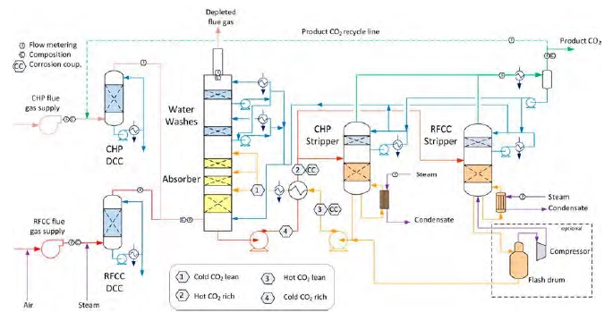
Figure 1: Illustration of TCM DA Amine plant and indication of rich and lean sections.
The test campaign was conducted from 06/07/2015 to 17/10/2015. During this period the plant treated mainly flue gas from the combined heat and power (CHP) plant. Separate testing were conducted for a period of 9 days from 16.09.2016 to 24.09.2016, where a mix of RFCC (0-10%) and CHP gas was utilized to study the effect of different flue gas conditions (CO2 and gas impurity concentrations) on mist formation. Typical CHP and RFCC gas compositions to the Amine plant are presented in Table 1.
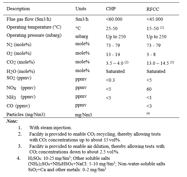
Table 1. Typical flue gas compositions to Amine plant.
The solvent used was 30 ± 2 wt % aqueous MEA. Pure MEA was diluted to desired concentration by adding demineralized water. An anti-foam agent was also used to reduce indication of foam in the stripper. Table 2 provides a comparative overview of compounds present in lean and rich solvent. Typical lean CO2 loadings in the 30 wt% aqueous MEA solution were ranging from 0.15 to 0.25 mole CO2 per mole MEA and typical rich CO2 loadings were ranging from 0.48 to 0.50 mole CO2 per mole MEA throughout the campaign.
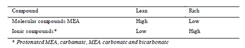
Table 2. Components present in lean and rich solvent.
Typical process parameters for the MEA solvent in circulation are presented in Table 3. There were marginal changes in both temperature and pH during the campaign. The solvent flow was approximately 55 tons/hour, except for a period of approximately 20 days where the flow was 80 – 120 tons/hour. During the test campaign there were two shutdowns, the first for one day and the second for seven days. In addition, there were two short periods during the campaign when the flue gas was not in contact with the circulating solvent due to planned or unplanned stops. Total test period lasted for 123 days. Operational hours are counted as hours with both flue gas and solvent circulation. The campaign gave a total of 1960 hours of operation.
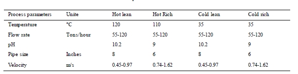
Table 3. Process parameters Amine circulation.
The main plant equipment and piping system in contact with amine consist of 22% Cr duplex. Gaskets used are mainly EPDM and PTFE. A few internal parts in valves are produced in Stellite and Inconel, while the absorber has packing and structure manufactured in SS 316L. The absorber is manufactured in concrete, but is internally lined with polypropylene material. These materials form the basis for the corrosion coupons chosen. Carbon steel nevertheless is included in the test program, although carbon steel is not used in the section in contact with amine. As a part of the internal TCM DA maintenance program, pipe spools in hot rich and lean section are inspected between each change of solvent inventory. Penetrant testing or x-ray is performed on pipe welding to check for any changes.
For corrosion several factors are important to monitor in the amine system; pH, temperature, velocity and heat stable salts[1].
3. Corrosion coupons and solvent analysis
3.1 Corrosion coupons
Table 4 presents the type of materials tested. The purpose and the locations in the plant are also listed.
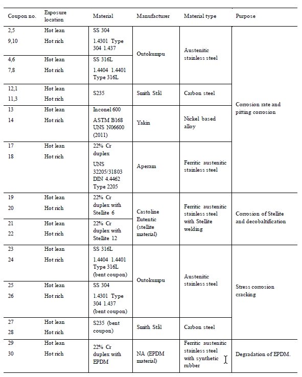
Table 4. Corrosion coupons installed in the amine plant.
The stainless steel, carbon steel and Inconel materials were cut out from larger plates using high pressure water. Stellite 6 and Stellite 12 were welded on duplex corrosion coupon surface according to supplier and welder recommendations. Purpose was to examine the corrosion resistance of the Stellite materials on duplex. Stellite is a cobalt-chromium alloy used as hard facing on machine parts. The EPDM material tested during the campaign was a gasket from equipment installed in the amine plant. A specific data sheet for the material is therefore not available. Coupons of SS 316, SS 304 and carbon steel where installed as both plain and bent coupons. The bent coupons were meant to simulate stress corrosion cracking [7]. Figure 2 and 3 presents the specimens mounted in the test rack exposed to the solvent.
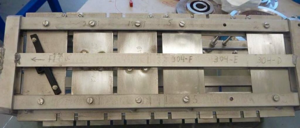
Figure 2: Illustration of coupons installed in the rack. Flow direction from right to left.
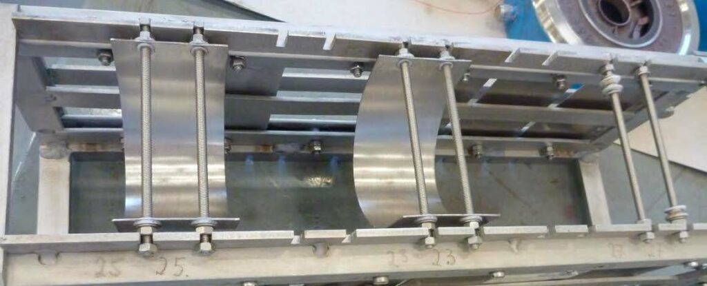
Figure 3: Illustration of bent coupons installed in the rack. Flow direction from right to left.
The corrosion racks are of alloy 316L and are placed longitudinally in the pipe. This means that some specimens are placed at the top side of the piping, while others are located at the bottom of the pipe. Bent coupons are placed at the side of the rack. To ensure that there is no contact between each coupon and the rack, PTFE insulators are mounted between the two materials. Table 5 and Table 6 illustrates where in the rack each coupon is installed.
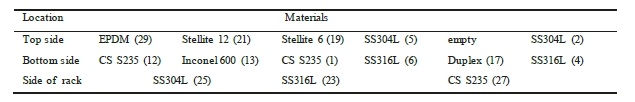
Table 5. Indicate coupon position in the lean rack, with number labelling. Flow direction from right to left.
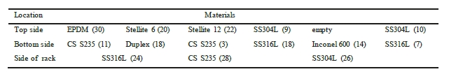
Table 6. Indicate coupon position in the rich rack, with number labelling. Flow direction from right to left.
Before installation, all coupons were carefully prepared. Smergel 80-600 were used to polish the surface. Coupons were thoroughly water washed and dried with absolute alcohol. After 24 hours in exicator, weight measurements were performed. For each sample type, one additional coupon was stored in a clean and dry environment as an unexposed reference. After exposure, each coupon was washed and weight determid by the same procedure as before exposure.
3.2 Corrosion coupon analysis
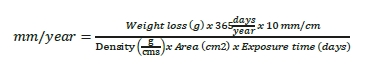
The weight losses were used to calculate the general corrosion rate in mm/year. All corrosion coupons had the same dimensions before exposure. Equation 1 was used to calculate the corrosion rate in mm/year.
The corrosion coupons were examined for local corrosion by microscopy at a magnification of 25X. The depth of the local corrosion was measured by use of Alicona scanning microscope.
The alloys Stellite 6 and Stellite 12 were examined by SEM (scanning electron microscopy) connected to EDS (Energy dispersive spectrometer) in order to identify “decobaltification”. The examination was performed at a magnification of 2000x.
The coupons prepared for stress corrosion cracking were examined for cracks by microscopy at a magnification of 40X and by use of dye penetrant fluid according to ASME B31.3.
Shore hardness, tensile testing (modulus and stress at break) and visual examination of fracture surfaces after tensile testing were performed on the EPDM material. Unexposed EPDM was examined as reference.
3.3 Evaluation criteria corrosion coupons
- General and pitting corrosion : The acceptance criterion for stainless steels for general corrosion based on weight losses is set to ≤ 0.1 mm/year and no pitting visible at a magnification of 25x. For carbon steel acceptance criterion is set to ≤ 0.1 mm/year and < 20 µm in local corrosion depths.
- Stress corrosion cracking: No visible cracking after dye penetrant testing is set as acceptable.
- EPDM: No significant difference in the results from the hardness and tensile testing of the unexposed and exposed EPDM.
- Stellite 6 and 12: No decobaltification shall be visible at a magnification of 2000x.
3.4 Solvent analysis
Previous experiences at TCM DA have shown an increase in iron, chrome and nickel ions measured in the circulating solvent. Monitoring the increase of metal ions in the solvent can therefore aid to discover possible corrosion attacks within the plant. Metal concentration was analyzed by ICP-OES frequently throughout the campaign. The solvent samples for analysis were taken from the cold lean amine.
The amount of HSS in the solvent is an important factor for corrosion evaluation in amine systems. Generally, low HSS concentration is recommended to keep amine CO2-capture capacity high and corrosion rate low, 0.5-0.8 wt% for long term and reclamation at a certain wt% of total HSS [8,9,10]. The HSS concentrations were determined as described elsewhere. [11]
4. Results and discussion
4.1. Corrosion coupons and solvent analysis
Table 7 shows the general corrosion rates and depth of pitting corrosion found on the coupons. The green and red colour in the cells is explained below the table.
As shown in the table, the corrosion rate was far below 0.1 mm/year and no pitting observed on the corrosion coupons in alloy 304L and duplex stainless steel exposed to both lean and rich solvent.
All the coupons in alloy 316L had corrosion rate below 0.1 mm/year. No pitting was observed on 316L coupons exposed in lean solvent, while three pits were found on each of the 316L coupons exposed to the rich solvent . Figure 4 shows pictures of two pits found on these coupons. The maximum pitting depth was 51 µm, corresponding to 0.15 mm/year.
The Inconel 600 coupon exposed in lean solvent was attacked by coarse general corrosion with a corrosion rate of 0.84 mm/year. No pitting was observed. In rich solvent the same alloy showed corrosion rate far below 0.1 mm/year and no pitting. To verify that both coupons were Inconel 600, analysis with “Niton alloy analyser” was performed on these coupons. The analysis performed showed that both coupons were of the same alloy.
The carbon steel coupons in S235 disappeared during the exposure time due to total corrosion. The corrosion rate for carbon steel, S235, is calculated to be above or equal to 1.4 mm/year based on the total weight prior to exposure.
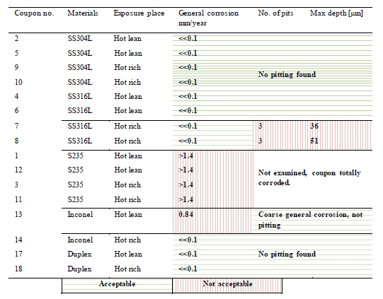
Table 7. General corrosion and pitting results.
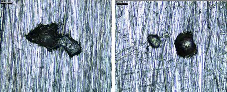
Figure 4. Pictures of pitting found on SS 316L coupon. Left picture illustrates pitting depth 51 µm at magnification 400x(coupon no. 8), while right illustrates depth 36 µm at magnification 160x(coupon no. 7). No similar pitting was found on the unexposed reference coupon.
No corrosion or degradation of the Stellite 6 and 12 material was observed in the SEM/EDS examination. There were no differences between the unexposed reference and the exposed coupons.
No stress corrosion cracking was observed on the 304L or 316L coupons after visual examination at a magnification of 40x nor after dye penetrant fluid examination.
There were insignificant differences between the unexposed reference and the exposed EPDM material based on the results from shore hardness and tensile testing. There was no visual difference in the fracture surfaces between the unexposed and exposed EPDM.
Figure 5 illustrates the ion concentration of metals in lean amine solvent. The aim of monitoring the metals in the solvent is to follow the increase of the metal ions. If a rapid increase would occur, inspection and evaluation of the cause(s) would have to be performed. In an amine plant some increase of metal ions is acceptable. Rennie (2006) informs that corrosion is typically worse at locations where the acid gases are flashed off, for example the regenerator reboiler [12]. In the reboiler and stripper section of the amine plant at TCM DA, fouling in the equipment and piping system is observed. This may be related to the boiling off of the solvent and the temperature at this location. The increase of metal ions might come from this hot section of the plant. However, internals within the absorber are manufactured in SS 316L, and might be affected by the process environment in the absorber. The flue gas from the CHP plant does not consist of considerable amount of metals. RFCC gas do contain a higher level of metals, but even with the mixed RFCC and CHP gas the metal ion concentration do not seem to have rapidly increased during the mixing period. This excludes that most of the metal ions measured in the solvent could originate from the flue gas during this MEA campaign.
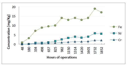
Figure 5: Metal ion concentration in lean solution. X-axis provides time of solvent analysis.
HSS are reported as the wt% of the equivalent amount of amine. This means if HSS concentration were 1 mole/kg (eq/Kg) of solution, it will be 6.1 wt% as MEA. Figure 6 illustrates the HSS wt% measured by titration during the campaign. Approximately 1.25 wt% HSS where measured at the end of the campaign, and the increase was close to linear.
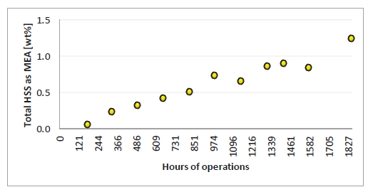
Figure 6. Heat stable salts measured by titration. X-axis provides time of solvent analysis.
The Inconel 600 coupon exposed in lean solvent was attacked by coarse general corrosion while in rich solvent the same alloy showed corrosion rate far below 0.1 mm/year. The reason for the high corrosion in lean solvent may be related to changes in chemical composition, pH or temperature. This campaign shows that Inconel 600 is not compatible with lean 30 wt% MEA at high temperatures ( ̴ 120°C), but that the critical temperature for corrosion may be lower, somewhere between 50-120°C. No corrosion was observed in the hot rich section in the same operational period.
There were some mechanical damages on the coupons which made it difficult to analyze pitting corrosion. A few pits were found on the 316L coupons while no pitting was found on SS304L. SS316L is placed against the bottom while SS304L is placed against the top of the pipe coil. In periods without solvent circulation it may have been some deposits that have covered the surface of SS316L which can increase the corrosion attacks. However, the lean coupons have not been affected by the shutdown periods.
Erosion and the velocity of the fluid is a factor influencing the corrosion rate. As listed earlier in Table 3, the velocity during the campaign is highest in the rich section. Rennie (2006) informs that the velocity limit for carbon steel is maximum 1.5 m/s, and that for stainless steel it is often one upper and lower limit [12]. Based on the relatively low average velocity in the piping where the coupons have been installed, erosion is not the main reason for the corrosion results. However, the corrosion racks are designed such that turbulent flow will occur around the coupons, and it can affect the corrosion rate.
The location for the corrosion coupons is mainly chosen due to the high temperature at that section within the plant. For future work TCM DA will try to install corrosion coupons in the cold rich and lean section, as well as in the hot section. This can evaluate if there are larger differences between the corrosion rate in the hot and cold section. Inspections of equipment and piping system are also future work that can help understanding and conclude on the corrosion and corrosion mechanisms that occurs in amine plants.
5. Conclusions
After execution of 30 wt% aqueous MEA campaign at TCM DA amine plant from July to October 2015, the following conclusions can be made according to the work conducted:
- The coupons in alloy S235, carbon steel, was totally corroded during the test period. The corrosion rate for carbon steel, S235, is calculated to be above or equal to 1.4 mm/year.
- The corrosion rate was far below 0.1 mm/year for all the coupons in alloy 304L, 316L and 22 Cr duplex stainless steel.
- The Inconel 600 coupon exposed in lean solvent was attacked by coarse general corrosion with a corrosion rate of 0.84 mm/year. In rich solvent the same alloy showed corrosion rate far below 0.1 mm/year.
- Pitting was not observed on coupons in 304L, Inconel 600 and 22 Cr Duplex.
- A few pits were observed on the 316L coupons exposed to rich solvent with a maximum pitting depth of 0.15 mm/year. No pitting was found on the same alloy exposed to lean solvent.
- No corrosion or degradation of alloy Stellite 6 and Stellite 12 was observed.
- No stress corrosion cracking was found on the 304L or 316L coupons.
- No degradation of EPDM (Ethylene propylene elastomer) was observed.
- HSS and metal ions are similar to previous MEA campaigns, and are concluded to be within acceptable limits.
Acknowledgements
The authors gratefully acknowledge the staff of TCM DA, Gassnova, Statoil, Shell and Sasol for their contribution and work at the TCM DA facility. The authors also gratefully acknowledge Gassnova, Statoil, Shell, and Sasol as the owners of TCM DA for their financial support and contributions.
References
- Kohl A, Nielsen R. Gas Purification. 5th ed. Houston: Gulf Publishing Company; 1997.
- Pearson P, Hollenkamp A F, Meuleman E. Electrochemical investigation of corrosion in CO2 capture plants – influence of amines. Electrochimica Acta 2013;110:514-516.
- Goff GS, Rochelle GT. Monoethanolamine Degradation: O2 Mass Transfer Effects under CO2 Capture Conditions. Industrial & Engineering Chemistry Research 2004;43(20): 6400-6408.
- Kittel J, Idem R, Gelowitz D, Tontiwachwuthikul P, Parrain G, Bonneau A . Corrosion in MEA units for CO2 capture: Pilot plant studies. Energy Procedia 2009;1:791-797.
- Verheyen TV, Adeloju SBO, Chaffee AL, Meuleman E. Primary sources and accumulation rates of inorganic and dissolved metals in a MEA absorbent during PCC at a brown coal-fired power station. International Journal of Greenhouse Gas Control 2015; 41:239-248.
- Cousins A, Ilyushechkin A, Pearson P, Cottrell A, Huang S, Feron PHM. Corrosion coupon evaluation under pilot-scale CO2 capture conditions at an Australian coal-fired power station. Greenhouse gases Science and Technology 2013;3:169-184.
- Field Corrosion Evaluation Using Metallic Test Specimens, NACE Standard RP0497-2004, Item No. 21083.
- Arthur L. Cummings, Scott W. Waite, Dennis K. Nelsen. Corrosion and Corrosion Enhancers in Amine Systems , MPR Services, 2005.
- Winyu Tanthapanichakoon, Amornvadee Veawab. Corrosion by heat-stable salts in amine-based CO2 capture unit. University of Regina, 2003.
- E.R. Baumeister, R. C. Souza, Carlos Ihle Rusque. Amine contamination and associated problems in gas treating units, AVPG, 2010.
- Morken AK, Pedersen S, Kleppe ER, W isthaler A, Vernstad K, Ullestad Ø, Flø NE, Faramarzi L, Hamborg ES. Degradation and Emission Results of Amine Plant Operations from MEA Testing at the CO2 Technology Centre Mongstad. Energy Procedia (GHGT -13), Forthcoming 2017.
- S. Rennie. Corrosion and material selection for amine service, Woodside Energy Ltd, 2006.