
2. CO2 Technology Centre Mongstad – Design, Functionality and Emissions of the Amine Plant (2011)
Gelein de Koeijer*a, Yngvil Engea, Knut Sandenb, Oscar Fr. Graffb, Olav Falk-Pedersenc, Tore Amundsenc, Sverre Overåa
a Statoil ASA, N-4035, Stavanger, Norway b Aker Clean Carbon N-0212, Oslo, Norway c TCM DA, NO-5954 Mongstad, Norway

Abstract

The CO2 Technology Centre Mongstad (TCM) project is constructing two large post-combustion CO2 capture demonstration plants near the Statoil operated Mongstad refinery, located at the Norwegian west coast north of Bergen. TCM’s partners are Gassnova, Statoil, Sasol and Norske Shell. This paper describes the amine plant. The amine plant is designed and constructed by the CO2 capture technology provider Aker Clean Carbon (ACC) with specifications and additional generic functionalities defined by TCM. Several new technology elements will be tested and verified, including improved solvents. Monoethanolamine and a new ACC solvent will be tested during the initial 16 months of operations. Thereafter tests will be run by the TCM partners. The quality and quantity of the emissions from the absorber to air have become top priority. Currently they represent a health and environmental uncertainty, mainly due to the lack of reliable and accessible experimental data. While knowledge and experience of these emissions are rapidly increasing, an emission permit is being applied for. The amine plant is highly flexible and can combine several novel technologies. Due to its scale it will give valuable information on utility and space requirements, scale-up properties and contribute to reducing HSE risks and costs.
1. Introduction
The CO2 Technology Centre Mongstad (TCM) project [1,2] is constructing two post-combustion CO2 capture test plants near the Statoil operated Mongstad refinery, situated at the Norwegian west coast north of Bergen. One unit will use amine technology and the other chilled ammonia technology. TCM’s partners are Gassnova (75,12% – representing the Norwegian State), Statoil (20%), Norske Shell (2.44%) and Sasol (2.44%). Statoil is the operator for the execution phase and has been selected as the operational service provider. The overall aims for TCM are:
- Test, verify and demonstrate CO2 capture technology owned and marketed by vendors
- Reduce cost, technical, environmental and financial risks
- Encourage the development of a market for such technology
- International deployment
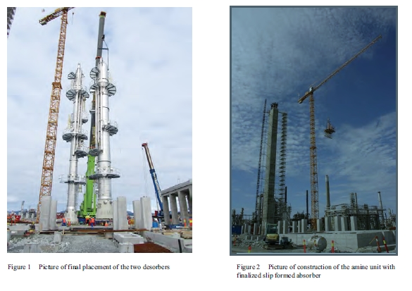
At the moment of writing, this project is one of the largest CO2 capture demonstration units under construction. It is highly flexible in order to obtain information about different CO2 capture technologies. The amine plant is designed and constructed by the CO2 capture technology provider Aker Clean Carbon (ACC) [3]. The plant is under construction (see Figures 1, 2 and 3) and start-up is scheduled for 2011. The selected ACC’s Advanced Carbon Capture Process [4] includes several special new features such as:
- New improved amines, which exhibit less degradation and reduce energy demand
- Emission control system, which gives minimum emission to air
- Rectangular concrete absorber with internal liner
- Energy saver, which reduces the steam demand
- Two desorbers with alternative reboiler designs
- Thermal reclaimer design, which gives minimum waste
TCM will be a driving force in the qualification of large-scale capture technology and development of improved technology. The aim of this paper is to describe the design and functionality of the amine unit, and to contribute to the international deployment of TCM.
2. Method of design
The concept for the amine plant was defined through an industrial stage-wise development, which started summer 2007. International competition between technology suppliers was used. The criteria for the competition were based on fulfilling TCM’s aims. A pre-qualification process reduced the number of suppliers. After a bidding round based on Front End Engineering & Design (FEED) studies, Aker Clean Carbon (ACC) was chosen for the detailed design and construction early 2009. The basis for design is ACC’s amine based CO2 capture technology developed over the last years [3,4,5] but adapted to specifications, functionalities and flexibility requirements defined by the TCM project. Several new technology elements will be tested and verified in the plant, including improved solvents.
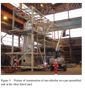
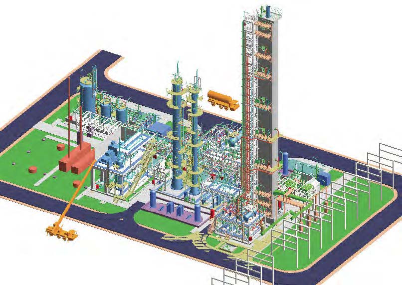
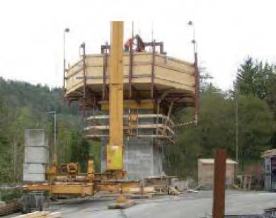
An important design strategy has been to utilize the same construction methods for the TCM plant as will be utilized for full scale plants. This can be exemplified by the absorber that has been slip formed, which is a great advantage for large constructions. Figure 2 shows the slip formed absorber at the Mongstad site. Another example is that the plant has been extensively modularized in order to prefabricate off-site. Figure 3 shows the construction of one of the reboilers on a pre-assembled unit at the Aker Stord yard, south of Bergen. This serves two main benefits; the productivity is generally greater at fabrication yards than site, and it is a risk reducing measure to minimize construction work close to complex sites as the Mongstad refinery.
3. Design and Functionality
3.1 Overall design
By fulfilling TCM’s aims specifically for the amine unit, the design has become one of the most advanced ones for amine plants with a high degree of flexibility. The process is an absorption/desorption process [3] and the overall design is shown by a 3D illustration in Figure 4.
The most important characteristic of the TCM facility is high flue gas flexibility by being able to capture CO2 from two different flue gas sources. This is a unique feature relative to other pilot and demonstration units of this size. The first flue gas is a slip stream from gas fired combined heat and power (CHP) flue gas with 3,5 vol-% CO2. This flue gas is representative of gas fired power plants. When using this flue gas the amine unit will have a capacity of 25 000 tonnes CO2/yr captured. The second flue gas is a slip stream from Residue Fluid Catalytic Cracker (RFCC) flue gas with 12,9 vol-% CO2.
This flue gas is representative of refineries, and also for coal fired power plants since it contains similar levels of SOx, NOx and particulates. When using this flue gas the amine unit will have a capacity of 74 000 tonnes CO2/yr captured. The unit is designed for 85% CO2 capture rate with CO2 purity of 99,9% for both CHP and RFCC flue gases. Furthermore, it will be possible to recycle captured CO2 to the CHP flue gas to achieve concentrations between 3,5 and 9% CO2 in the CHP flue gas. This will enable to test the effects of Exhaust Gas Recycle (EGR) [6] on amine based CO2 capture. The critical areas of interest for the technology include determining solvent degradation and process energy demand.
It will be possible to operate with large turn-downs. The design specification is 50% for both flue gasses which means a possible range of 16–100% for the CO2 product rate. Turn-down behaviour is especially important for quantifying load following capabilities and general flexibility. Relative to other capture technologies of pre-combustion and oxyfuel, this flexibility is said to be one of the important advantages of post-combustion [7]. The most interesting issues to be studied are the liquid distributor capacity and the vapour/liquid distributions in the packings.
Further, the flue gas treatment system upstream of the absorber allows for control and adjustment of flue gas temperature and water content. This allows the absorber inlet to be operated from 25 °C and up to more than 50 °C.
The utilities (steam and electricity) and tie-ins (ducts, blowers, flue gas coolers) are designed for 120% capacity to be able to test plant limitations. Normal design of CO2 capture units contains design margins. Currently these design margins have an uncertainty in the same range as the best available models. This uncertainty is estimated to be 10-20% [8]. Control of design margins is important for designing with minimum investment cost.
CO2 compression and storage is not included at this stage but may be added in a later phase.
3.2 Sampling, measurement and analysis
Being a demonstration unit where knowledge is the main product, extensive analyzers and monitoring instruments for measuring the improvements with high accuracy will be installed. The most important variables will be measured online where possible. The design includes many manual sampling points in order to be able to perform more detailed analyses. Special focus has been on emissions to air from the absorber (see Ch.4). It will be possible to fully define and where possible over-define the mass and energy balances in the unit in order to verify simulation models. In the absorber outlet and CO2 product temperature, pressure, flow, composition (CO2, N2, O2, Ar, H2O, NOx, SOx, amines, NH3, some degradation products) will be measured online. Corrosion coupons spool pieces are being installed to evaluate the use of other desorber, absorber, heat exchanger and piping construction materials than the ones used.
3.3 Solvents
The plant is designed to be able to test different solvents. ACC has scheduled to test the following:
- 30 wt% MEA (monoethanolamine) solution for 4 months, which is a well known solvent [9, 10]. The performance guarantees from ACC are based on this solvent. The results will give a benchmark for the novel solvents.
- improved solvent which contains mixtures of primary, secondary and tertiary amines developed by ACC and partners
The solvents will be tested both on RFCC and CHP flue gas. The improved solvent has demonstrated low degradation and reduced reboiler duty in tests at a coal-fired power station in Scotland (ref. section 3.6). A test program will be set up for obtaining best possible data, knowledge and experience.
3.4 Absorber
The absorber has a unique design and flexibility, see also Figure 5. The design philosophy from TCM was that it should enable testing of most amine based technologies. ACC has designed the absorber together with Koch-Glitsch as packing supplier. The CO2 absorption part has three packing sections for enabling 85% CO2 capture with slow and fast amines from RFCC, CHP flue gas and CO2-enriched CHP flue gas. The lowest section is the tallest one with two shorter sections above it of similar heights. Lean amine can be fed at the top of each section, but only above one section at a time.
The absorber design is part of ACC’s technology. The outer wall is rectangular (internal dimensions: 3,5x2x62 m) made of concrete with internal polymer lining. TCM will have the first lined concrete absorber in the world for CO2 capture from flue gasses with amines. The wall is slip formed with the liner continuously installed during the slip forming. The wall is penetrated extensively for various inlets, outlets, sampling points and online measurement instrumentation. The pressure drops will be measured over each packed section and the temperature will be measured every rising meter at a grid of horizontal locations. The outlet of the absorber is a conventional circular pipe (1 m diameter, 4 m height) with various penetrations for online Fourier transform infrared (FTIR) spectroscopy concentration measurement and iso-kinetic sampling. The flue gas inlet is designed with the aid of computational fluid dynamics to ensure proper gas distribution.
The wash section consists of water wash packings with demisters above and below. The water wash is designed such that ACC’s novel emission control system can be tested. There is a possibility of installing additional demisters. Relative to normal practice, this section may seem overdesigned. The reason is to quantify the emissions to air by experimenting with various washing configurations. This will contribute to reducing the residual health & environmental risk to an acceptable level.
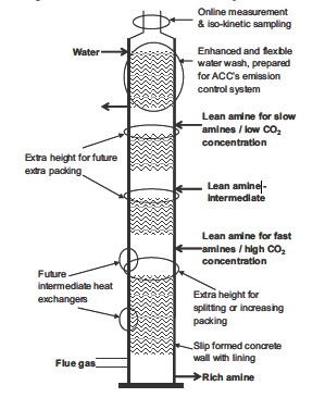
The division of CO2 absorption sections can be modified in the future. The lowest tallest section can be divided into two.the section improve the liquid/vapour distribution. Moreover, each of the 3 sections has a possibility of 10% increase in packing heights by adding extra height between liquid distributor and packing section.
By the addition of extra inlets, internal brackets and other provisions of extra distributors, it is also possible to add an intermediate heat exchanger at two different heights.
3.5 Desorbers and Reclaimer
TCM’s amine unit has two strippers or desorbers, enabling operation with minimum energy demand with both flue gases. Moreover two desorbers are needed to meet the turn-down requirements. ACC has designed the desorbers using Koch-Glitsch as packing supplier. The diameter of the RFCC desorber is 2,2 m and for the CHP desorber 1,2 m. Both desorbers have one packed section for CO2 desorption and one for water wash above the rich amine inlet. Height is reserved and penetrations are made for the possibility to split the CO2 desorption section for future installation of split flow and/or better vapour/liquid distribution. The pressure in the desorbers can be increased and reduced. Pressure variation tests can reveal the optimum compromise between steam demand, steam quality, compressor requirement and degradation for each solvent and flue gas.
Each desorber has its own reboiler which is designed for current scheduled operation. Each desorber can be fitted with a second reboiler in case another type of operation is decided, or new or optimized types of reboilers are developed.
The RFCC desorber has installed ACC’s technology for recovering energy in pressurized hot lean amine [3]. The CHP desorber does not have such an Energy Saver, but provisions are made for future installation. The Energy Saver converts low value energy into useful stripping energy and includes heat integration. This Energy Saver requires more electricity but less steam, and leads overall to reduced energy demand.
The reclaimer will be a thermal reclaimer with external steam heating. It will be used initially for getting data and experience, which is scarce for reclaiming. It is possible to upgrade the current reclaimer for reduced pressures. Valves are installed and place is reserved for a future 2nd reclaimer with improved technology.
3.6 Mobile test unit
In the initial period of operations, ACC’s Mobile Test Unit (MTU) will be installed at the Mongstad site, and will be used for tests in parallel to the larger unit. It has an absorber diameter of 0,4 m, a height of 25 m, and a capture capacity of 0,2 t CO2/hr on flue gas from coal fired power plants. It has been operated in Risavika Gas Centre (Norway) on flue gas from a gas turbine and in Longannet (Scotland) on flue gas from a coal fired power plant as part of the SOLVit R&D project [5]. It will be used to gain early test results and experience from operation on two different flue gas sources with new amines. However, such tests lack the large-scale effects and some of the flexibility of the larger scale unit. The combination of results from both units will be synergetic.
4. Emissions to Air
The quality and quantity of the emissions to air have become top priority. Currently they represent a health and environmental uncertainty, mainly due to the lack of reliable and accessible experimental data. A new emission control system will be tested in the TCM amine absorber. The system has the potential to reduce the emission of amines and degradation products to a minimum. A large part of the efforts in this project went into assessing the assumptions on the formation, dispersion and acceptance criteria of carcinogenic nitrosamines. Nitrosamines are assumed to be formed from reactions between secondary/tertiary amines and NOx, both in the absorber and in the atmosphere. There are several, major uncertainties in the selected nitrosamine assumptions, such as formation time and conditions, stability, and resulting concentration levels in the plant and surroundings. Formation of nitrosamines has been experimentally observed in laboratory experiments [10]. New knowledge is being rapidly generated and various experiments are being executed [10, 11, 12, 13]. In this continuously changing situation, TCM is applying for an emission permit to the Norwegian authorities in the summer of 2010 [13]. This application is the world’s first application for a larger scale amine unit that addresses the emissions in detail, and can be considered as pioneering work. In short, the procedure of writing this permit consisted of obtaining:
- The best possible estimates of the emissions from ACC, i.e. an environmental budget. Qualitative measurements, analogies and theory were used for estimating the emissions. The estimates were given in the form of scenarios in order to capture the whole range of operations, including high values during upsets and low values which are expected from theoretical calculations. As an example, the estimates for two scenarios (expected and design) for MEA for CHP and RFCC flue gasses are given in Table 1 for three of the main emitted components. The expected values are the most likely ones normal operation will be below. The design values are those used for the design described earlier in this paper. As can be seen in the Table, the design values are already conservative relative to the expected values. The estimates are based from measurements at the MTU. Other components that have been observed in the measurements from the MTU are formaldehyde, methylamine, ethylamine, dimethylamine, formic acid, acetic acid, butyric acid, propionic acid, n-(2-hydroxyethyl)imidazole, n-(2- hydroxyethyl)-formamide and nitrosamines as a group. In addition, it is likely that ketones, amides and other secondary amines will be present.
| Expected (ppmv) | Design (ppmv) | |||
| CHP | RFCC | CHP | RFCC | |
| MEA | 0.5 | 0.5 | 1 | 1 |
| NH3 | 2.6 | 16.5 | 5.1 | 33 |
| Acetaldehyde | 1.3 | 0.825 | 2.55 | 1.65 |
Table 1 Estimate of 3 concentrations of emissions from absorber in the expected and design scenarios for CHP and RFCC flue gasses using MEA.
- Health, safety and environmental data on all amines and their degradation products, i.e. biodegradability, ecotoxicity, acute toxicity, mutagenicity, reproduction toxicity, irritation/corrosion, sensitation, repeated dose toxicity. ACC used SINTEF as consultant for this work, including searching the International Uniform ChemicaL Information Database (IUCLID), the ECOTOX database of the US Environmental Protection Agency (EPA), the BIODEG database of the Syracuse Research Centre (SRC), and the GENETOX database (EPA). Data for all components need to be collected, even if the amine or its degradation product is non-volatile giving negligible emissions. Operators can still come into contact with it during operations like reclaiming, filter change, sampling etc.
- Acceptance criteria and exposure limits for all amines and their degradation products in air and drinking water by searching
Norwegian and international HSE regulations and using the new REACH regulation from the European Union.
- Dispersion modelling results for all amines and their degradation products in air and drinking water. This work was done by Norwegian Institute for Air Research (NILU) and used input from all previous activities.
Due to the mentioned uncertainty the precautionary and worst case principles have been used actively, which has lead to the use of several assumptions. An important assumption is on how much of the emitted amine reacts with NOx in the atmosphere to nitrosamines. It is assumed that 2-10% of all emitted secondary and tertiary amines are transformed instantaneously into nitrosamines [13]. It is further assumed that the formed nitrosamines are 100% stable in the atmosphere and will not decrease. This is a precautionary approach which is recommended at this stage. R&D on this assumption has started [13] but there is still little published experimental and theoretical evidence. As yet, Norway does not have acceptance criteria for nitrosamines in air and drinking water. Hence, information from outside Norway had to be assessed. It was decided to use the criteria from the nitrosamine with the lowest concentrations found in EPA/IRIS for all nitrosamines, i.e. a group approach. These were found for N-nitrosodimethylamine, and are 0.07 ng/m3 for air 0.7 ng/l for drinking water [14].
After the data gathering and modelling an application was written for certain emission rates that satisfy the acceptance criteria. Such rates are meant to give flexibility for performing the desirable tests. Hence, they are not actually measured rates but aggregated numbers with contingencies. It is expected that new knowledge will elucidate the validity and level of conservatism of the numbers and assumptions in the application. However, they are considered to be the most valid ones with current available knowledge. For other future applications of these assumptions it is recommend to critically re-assess them with the most recent knowledge.
5. Technology Qualification
A structured technology qualification program is being executed for reducing the technology risks to an acceptable level for such a demonstration unit. The work consisted of making a qualification basis, technology assessment, failure mode identification and risk ranking, and selection of qualification methods. The technology qualification program has been designed by ACC with DNV as consultant, and has followed a specific procedure for CO2 capture presented in earlier published work by DNV [15]. These guidelines were developed in an R&D Joint Industry Project (with Aker Solutions, Aker Clean Carbon, Statoil, Statkraft, and DNV as partners). They are now used in an industrial environment for the first time. The detailed results are an important part of ACC’s competitive knowledge. The main technology risks were related to the emissions to air and absorber construction and functionality. Hence, the ongoing execution of the qualification methods is mainly focused on reducing these risks. A good example is the construction of a mock-up of the slip forming platform for the absorber, see Figure 6. With this mock-up the slip forming technology was tested before it was used in spring 2010 for the actual absorber.
This mock-up has contributed to the 62 m high concrete absorber being successfully raised within 20 days by the tested slip forming method.
6. Conclusions
An amine demonstration unit is being constructed at the CO2 Technology Centre Mongstad, located north of the city of Bergen in Norway. At the moment of writing, this unit will be one of the largest demonstration units for experimenting with amine technology. The design is highly flexible with an absorber with multiple sections and two desorbers with different diameters. Ample provisions for future improvements are also included. The unit can capture flue gasses representative of gas and coal fired power plants, as well as petrochemical plants and refineries. The technology supplier is Aker Clean Carbon and several new design features will be tested. Due to its scale it will give valuable information on utility and space requirements, scale-up properties and contribute to reducing HSE risks and costs. 30 wt% MEA and a new solvent developed by ACC and partners will be tested during the initial 16 months of operations. Subsequent testing will be done by the TCM partners. Construction technologies that may reduce construction cost of large scale units are also included. In parallel a much smaller Mobile Test Unit will be used for faster and cheaper tests that can benefit the test at the larger unit.
The quality and quantity of the emissions to air have become top priority. Currently they represent a health and environmental uncertainty, mainly due to the lack of reliable and accessible experimental data. New knowledge is being rapidly generated and various experiments are being executed. In this continuously changing situation, TCM is applying for an emission permit to the Norwegian authorities. It is expected that new knowledge will elucidate the validity and level of conservatism of the numbers and assumptions in the application. However, they are considered to be the most valid ones with current available knowledge.
Another novelty in this project is the use of recently developed guidelines for technology qualification of CO2 capture technology.
7. References
- De Koeijer GM, Enge YO, Thebault C, Berg S, Lindland J, Overå SJ. European CO2 Test Centre Mongstad –Testing, verification and demonstration of post-combustion technologies, Energy Procedia 2009;1:1321-1326
- Website on CO2 Technology Centre Mongstad www.tcmda.com (accessed July 2010)
- Aker Clean Carbon website, www.akercleancarbon.com (accessed July 2010)
- Oscar Fr. Graff, European CO2 Technology Centre Mongstad – Advanced Amine Carbon Capture Plant, Trondheim CCS-5 international conference 2009, http://www.energy.sintef.no/arr/CO2_2009/Presentations/B3-3.pdf (accessed July 2010)
- Website on SOLVit program, http://www.akercleancarbon.com/section.cfm?path=418,465 (accessed July 2010)
- ElKady AM, Evulet A, Brand A, Ursin TP, Lynghjem A. Application of Exhaust Gas Recirculation in a DLN F-Class Combustion System for Postcombustion Carbon Capture. J. Eng. Gas Turbines Power 2009;131;3:034505-[7]
- Lucquiaud M, Chalmers H, Gibbins J. Capture-ready supercritical coal-fired power plants and flexible post-combustion CO2 capture, Energy Procedia, 2009;1:1411-1418
- Luo X, Knudsen JN, De Montigny D, Sanpasertparnich T, Idem R, Gelowitz D, Notz R, Hoch S, Hasse H, Lemaire E, Alix P, Tobiesen FA, Juliussen O, Köpcke M, Svendsen HF. Comparison and validation of simulation codes against sixteen sets of data from four different pilot plants. Energy Procedia, 2009;1:1249-1256
- Knudsen JN, Jensen JN, Vilhelmsen PJ, Biede O, Experience with CO2 capture from coal flue gas in pilot-scale: Testing of different amine solvents, Energy Procedia, 2009:1;783-790
- Fostås B, Sjøvoll M, Gangstad A, Nenseter B, Pedersen S, Sørensen AL, The flue gas degradation chemistry of MEA based solvents, Submitted to Proceedings of GHGT-10 Amsterdam Sept 2010
- Lepaumier H, Da Silva EF, Einbu A, Grimstvedt A, Knudsen JN, Zahlsen K, Svendsen HF, Comparison of MEA degradation in pilot-scale with lab-scale experiments. Submitted to Proceedings of GHGT-10 Amsterdam Sept 2010
- Website for R&D project “Atmospheric Degradation of Amines” – ADA http://ada.nilu.no/ (accessed July 2010)
- TCM. Application for emission permit with appendices, to be published on www.klif.no (Norwegian) 2010
- EPA/IRIS database entry for N-Nitrosodimethylamine, http://www.epa.gov/ncea/iris/subst/0045.htm (accessed July 2010)
- Myhrvold T, Helle K, Johnsen K, Hussain A. Development of a guideline for the qualification of CO2 capture technology, Energy Procedia 2009;1:1527-1534