
1. Results from testing of a Brownian diffusion filter for reducing the aerosol concentration in a residual fluidized catalytic cracker flue gas at the Technology Centre Mongstad (2018)
Gerard Lombardoa,c*, Muhammad Ismail shaha,c, Berit Foståsb, Odd Arne Hvidstenb,c, Leila Faramarzib,c, Thomas de Cazenovec, Hélène Lepaumierd, Pieter Rogiersd
aGassnova SF, Dokkvegen 10, 3920 Porsgrunn, Norway bEquinor ASA, PO Box 8500, 4035 Stavanger, Norway cTechnology Centre Mongstad, 5954 Mongstad, Norway dLaborelec, Rodestraat 125, 1630 Linkebeek, Belgium *Corresponding author
Abstract
Operation of amine absorbers with a flue gas containing sulfuric acid aerosols and dust particles is a challenge. After the installation of a Brownian diffusion filter upstream the absorber the aerosols are reduced and TCM has been able to operate the amine plant with the residual fluidized catalytic cracker flue gas. The Brownian diffusion filter efficiency is assessed based on the number particle concentration and aerosol size distribution. The tests at TCM demonstrate that more than 95 % of the aerosols were removed. The growth of the aerosols with moisture from the flue gas is fast and is not detected by the instrumentation installed at TCM. The water captured by the Brownian diffusion filter confirms that the mass concentration of the aerosols captured is between 1000 and 5000 mg/Sm3 of flue gas.
1. Introduction
The Technology Centre Mongstad (TCM) is the world’s leading facility for verifying and improving CO2 capture technologies. TCM is located at Mongstad, one of Norway´s most complex industrial facilities. TCM has been operating since autumn 2012, providing an arena for qualification of CO2 capture technologies on an industrial scale. In autumn 2017, Gassnova (on behalf of the Norwegian state), Equinor (formerly Statoil), Shell and Total entered into a new ownership agreement securing operations at TCM until 2020. The owners of TCM started their most recent monoethanolamine (MEA) test campaign in June 2017 where a large number of public, industrial, research and academic stakeholders were involved [1]. The campaign included demonstration of a model-based control system, dynamic operation of the amine plant, investigating amine aerosol emissions and specific tests targeted at reducing the cost of CO2 avoided. Through the testing, both flue gas sources currently available at TCM were used. These sources are the combined cycle gas turbine (CCGT) based heat and power plant (CHP) and the residual fluidized catalytic cracker (RFCC). They provide flue gases with a wide range of properties and a CO2 content from 3.6 to 14 %. TCM is located next to the Equinor refinery in Mongstad. The Mongstad refinery is the source of both flue gases supplied to TCM.
During the MEA campaigns in 2017 and 2018 TCM executed a series of tests to capture CO2 from residual fluidized catalytic cracker flue gas. It was first of its kind test campaigns at TCM where CO2 is captured from RFCC flue gas treated with a Brownian diffusion filter. A previous MEA test campaign was conducted while capturing CO2 from combined cycle gas turbine flue gas mixed with RFCC flue gas and recycled CO2. A pilot Brownian diffusion filter was tested in this previous campaign. Results of the previous campaign are documented at the GHGT-13 [2]. The new learning’s related to the Brownian filter efficiency and aerosol properties are reported in this paper. These learning’s are valuable for the design of flue gas treatments upstream or downstream of amine absorbers. The impact of flue gas pretreatment by the BD filter on the MEA emissions is reported separately [3].
2. Process description
In December 2016, a Brownian diffusion filter was installed between the RFCC direct contact cooler (DCC) and the amine absorber. The vessel for the Brownian diffusion Filter includes a high efficiency demister and twenty-one filters filled with fibers typically called candles. A simplified sketch of the BD filter unit is given in the figure 1.
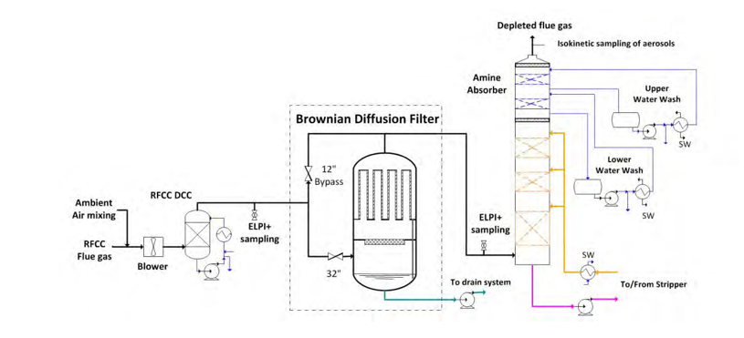
Figure 1. Simplified flow diagram of the Brownian diffusion Filter.
A detailed description of the BD filter unit is given in the following sections.
2.1 Functional description of the BD filter and design capacity
The main design parameters are:
- Design flue gas flow rate: 35,000 Sm3/h
- Maximum allowable differential pressure of the demister: 12 mbar
- Maximum allowable differential pressure of the candles: 30 mbar
Based on the operation experience acquired since the installation of the filter, a maximum RFCC flue gas flow of 40,000 Sm3/h to 45,000 Sm3/h is possible but the filter efficiency is slightly reduced.
The particles are captured by fibers and each particle captured grows by further accumulation until droplets are formed. When the weight of the droplets is sufficient, a water film occurs, flowing down to the bottom of the candles. During operation, the candles are partly filled with the water accumulated. The liquid collected downstream the candles is drained to the bottom of the vessel. A pump controls the level of the vessel.
2.2 Typical aerosol description at TCM
The table 1 describes the total number concentration and weight concentration of aerosols in the flue gas.
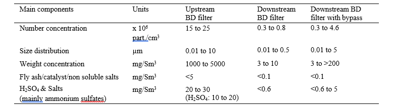
Table 1. Typical aerosol parameters at TCM.
Upstream the filter, the RFCC flue gas contains a high number of particles between 10 nm and over 5 µm diameter, and the composition is expected to be similar to the flue gas from a coal power plant without fabric filters. As illustrated in figure 2 the particle size distribution is variable upstream the BD filter. The variation of aerosol size distribution is caused by the fluctuations of the operation parameters of the refinery and mainly by the steam injection in the flue gas upstream of the RFCC DCC. At TCM, the steam injection is necessary in order to keep the temperature and moisture constant in the flue gas. The size distribution of the RFCC flue gas has been checked during several campaigns, before the installation of the BD filter, upstream and downstream the RFCC DCC and downstream of the absorber. The similarity between the measured size distributions suggests that a BD filter may be also applicable at the absorber outlet.
The flue gas composition downstream the candles at TCM is expected to be similar to coal flue gas treated with a conventional electrostatic precipitator and an additional flue gas purification unit as a fabric filter or advance purification systems as a wet electrostatic precipitator (WESP). The BD filter bypass allows higher particle concentrations to the absorber.
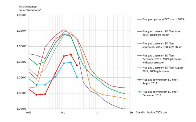
Figure 2. Typical size distribution upstream and downstream the BD filter.
2.3 Installation and mechanical design of the candles
The entire vessel including candles and demister is designed and delivered by Begg Cousland Envirotec Limited (United Kingdom). The candles are fixed to a main support plate as described in figure 3. The flue gas inlet is located at the bottom of the vessel, upstream of the demister and the flue gas is distributed to each candle through the openings in the main support plate.
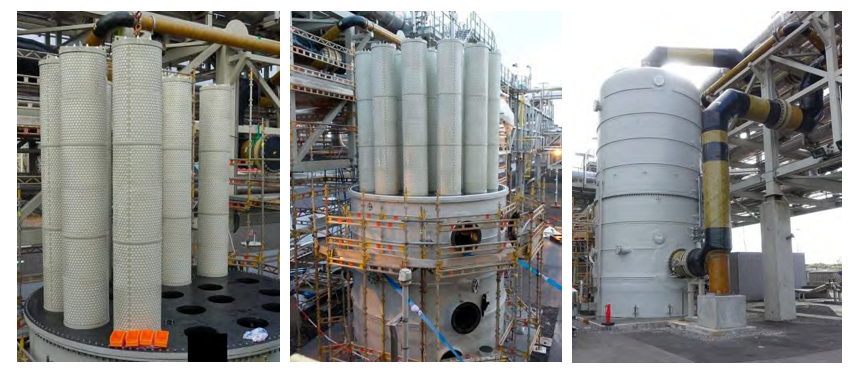
Figure 3 Installation pictures. To the left: main support plate of the candles. To the right: the flue gas inlet is located at the bottom of the vessel.
An isometric view of the RFCC flue gas treatment system is presented in figure 4. The bypass to the filter is located in the pipe rack. In order to minimize the capture of aerosols above 1 µm to the bypass, the connection of the bypass to the main duct is not isokinetic (branch tee) and the velocity to the bypass is low compared to the main flow to the filter.
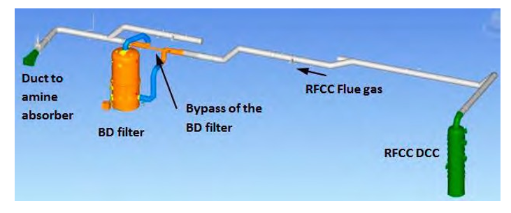
Figure 4. Isometric view of the RFCC flue gas treatment system.
2.4 Candle description
The thickness of the candle bed fibers is 50 mm and the total filtration area of the 21 candles is 135 m2. The inlet velocity to the filtration area is 7.2 cm/s. The design is optimized, based on the results from the pilot tests from various fiber types and suppliers.
The capture efficiency of the BD filter is approximately 97 % of the particle number based on 35,000 Sm3/h of flue gas with 20 x 106 particles/cm3. The number concentration downstream the candles is 0.3 x 10⁶ particles/cm3 with clean candles and 0.7 x 10⁶ particles/cm3 with used candles. The capture efficiency of the particles with a diameter between 10 nm and 70 nm is decreasing with higher flue gas flow. The life span of the candles may be reduced by the accumulation of catalyst particles. The life span of the candles shall be confirmed by further tests at TCM.
2.5 Installation and mechanical design of the demister
The demister installed upstream the candles is described in figure 5. The purpose of the demister is to minimize the catalyst particles accumulation in the candles. A Scanning Electron Microscopy with an Energy Dispersive X- ray spectrometer (SEM-EDX) was used to measure the elemental composition of the deposits and catalyst in the aerosols. As the catalyst particles are mainly detected in aerosols of 1 µm or above, a high efficiency demister is required.
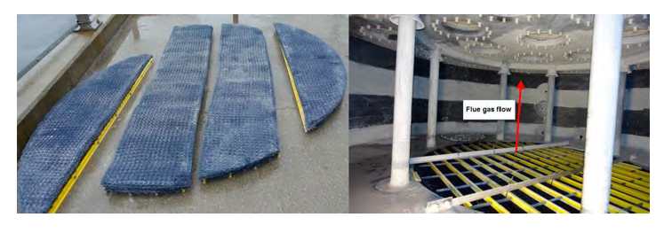
Figure 5. High efficiency demister. To the left: demister pads disassembled for cleaning operation. To the right: the demister pads are located under the yellow support grid. The candle support plate with the openings to the candles is visible at the top of the picture.
The demister is 2.45 m diameter, 120 mm thick and includes several diverse layers of polypropylene mesh. The demister is arranged in five sections and each section divided in a lower and upper bundle. The inlet velocity to the demister is 2 m/s. A demister is usually designed to remove liquid particles, but at TCM the demister is operated with catalyst particles and the demister requires periodic cleaning. At 35,000 Sm3/h, the mass of catalyst particles captured in the vessel is between 1 and 2.5 kg/day. Dry or accumulated catalyst particles require a disassembling of the demister and a manual cleaning with pressurized water. A cleaning is typically performed after a campaign period of 2 months. The operation parameters of the demister are critical in order to avoid dry areas and accumulation of catalyst. The accumulation of catalyst is likely limited at high water load and flooding conditions in the demister bed. A complete spare part of the demister is available at TCM in order to minimize the shutdown period during cleaning operation. A shutdown of 4 to 6 hours is usually necessary for a replacement of the demister.
3. Campaigns and test summary
A brief overview of the different tests conducted is given below and test results are detailed out in the following sections.
- From 16 to 22 December 2016: BD filter start-up/test and efficiency measurements with the use of ELPI+ (Electrical low pressure impactor: refer to section 6)
- From 24 to 30 January 2017: pressure drop tests of BD filter
- From 21 February to 25 April 2017: BD filter tests and proprietary solvent campaign with RFCC flue gas
- From 24 July to 17 November 2017: BD filter tests, MEA 3 test campaign and efficiency measurements with the use of ELPI+
4. Demister and Candle filter pressure drop
The pressure drop test results for are summarized in the table 2. At constant temperature and gas phase composition, the pressure drop through the candles and the demister is directly proportional to the flue gas flow and increasing with the mass of aerosols captured.
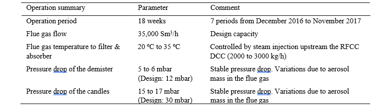
Table 2. Demister and Candle filter pressure drop
The efficiency of the demister secures a lower pressure drop of the candles than measured during the pilot tests in 2015. The water load in the demister and the accumulation of catalyst particles establish flooding conditions in the demister and high capture efficiency for aerosols above 1 µm. Due to the flooding conditions, water droplets are entrained from the demister to the candles.
The accumulation of catalyst particles in the candles is confirmed by the inspections of January, April, August and November 2017. However, the accumulation looks limited and no increase of pressure drop is observed. The life span of the candle will be estimated during the future campaigns with RFCC flue gas.
5. Mass of aerosols captured based on the liquid level measurements of the BD filter vessel
The mass of aerosol captured by the demister and the candles is estimated based on the liquid level measurement of the BD filter vessel.
The liquid accumulation in the filter vessel may be caused by:
- Aerosols captured
- Water condensation from the flue gas in the ducts and in the BD filter vessel. Based on the temperature decrease between the DCC and the inlet to the absorber, the maximum water condensation is estimated to 30 kg/h. A water condensation of 10 to 20 kg/h is confirmed during the tests with ambient air instead of flue gas.
- Liquid entrainment from the DCC. The tests with ambient air from 20,000 Sm3/h to 55,000 Sm3/h confirm that there is no entrainment of liquid from the DCC if the flow rate is limited to 45,000 Sm3/h.
At the design flow of 35,000 Sm3/h, the estimated capture rate is summarized in the table 3. The average concentrations of sulfate salts and sulfuric acid are based on laboratory water analysis from the vessel.
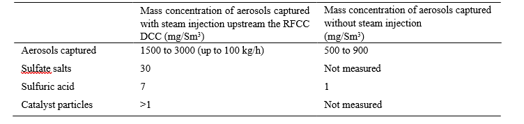
Table 3. Mass concentration of aerosols captured.
As described in the section 8, the mass concentration of water in the aerosols captured is higher than estimated with the ELPI+ measurements (50 to 500 mg/Sm3). A substantial number of aerosols with a diameter between 2 and 10 µm are necessary to explain the mass of aerosols captured in the vessel. The capture rate measured by the liquid level of the vessel confirms that the ELPI+ is not designed for the detection of large aerosols mainly composed of water. The salts and sulfuric acid concentrations are in accordance with the previous flue gas measurements between 2013 and 2015. Most of the catalyst particles are eliminated with the vessel drain and the mass cannot be estimated. A mass concentration of 1 to 3 mg/Sm3 of catalyst particles is estimated based on the previous flue gas isokinetic gravimetric sampling.
6. ELPI+ technology
6.1 Introduction
Based on weight concentration, the high efficiency of Brownian diffusion filters is well established. Most of the authority regulations are based on weight concentration and manual isokinetic sampling. The weight of aerosols under 0.5 µm is insignificant, but these aerosols may grow in the absorber, hence the efficiency based on weight is not satisfactory for amine absorbers. Therefore, the efficiency of the Brownian diffusion filter has been determined based on the particle number concentration and particle size distribution measured upstream and downstream the BD filter unit. The particle number concentration and particle size distribution are estimated with ELPI+ measurements performed by Engie Research and Technologies.
Working principle of the ELPI+:
- Particle charging
- Size classification in a cascade impactor (14 size classes)
- Electrical detection with sensitive electrometers
6.2 ELPI+ description and limitations for the measurements of aerosols with high load of water
As described in the figure 6, the ELPI+ measurements require usually a dilution of the sample with dry air in order to avoid water condensation on the EPLI+ stages. The particle size distribution and number concentration may be modified by this dilution if the aerosols contain large particles with mainly water.
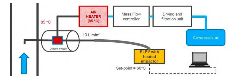
Figure 6. ELPI+ sampling system.
In the range of 10 nm to 1 µm, the ELPI+ (Electrical low pressure impactor) is applicable to estimate the efficiency of the Brownian diffusion filter based on the particles number concentration, but the impact of following limitations shall be evaluated during the measurements:
- Impactor loading: if a measurement continues a long period or sampling is made from a high particle concentration, the high amount of collected particles can have a negative effect on the impactor performance. As a rule of thumb, 1 mg of particles per one impactor stage can be used as an absolute maximum value.
- The sampling to the ELPI+ is not isokinetic upstream the filter. With the dilution system used, an isokinetic sampling to the ELPI+ is not reliable or complex. However, as demonstrated by previous studies [4, 5], the effect of non-isokinetic sampling of aerosols on the observed sizes is not important since most of the aerosol size is smaller than 0.5 µm.
- Fine Particle Correction: diffusion causes the impact of the smallest particles on a too early stage, leading to an overestimation of the particle size. An algorithm is used to correct the ELPI+ readings. It is possible to calculate both uncorrected and corrected particle size distributions.
- Aerosols above 2 µm, composed only of water are unstable and easy to evaporate. This type of aerosols may be a challenge for ELPI+ measurements.
7. Results from ELPI+ measurements just after the first startup of the BD filter
The ELPI+ measurements completed just after the first startup of the BD filter are summarized in the table 4.
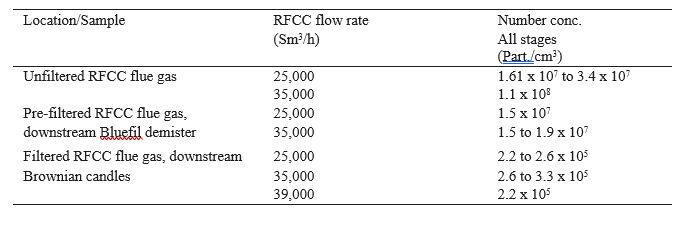
Table 4. ELPI+ measurements of December 2016.
Comments to the results:
- Relatively large variations are measured for the RFCC flue gas, as previously observed since the first measurements in 2015: from 12 to 34 million particles/cm3
- Due to turbulent weather conditions with outdoor sampling with the ELPI+, unstable measurements are experienced.
- As the particles above 1 µm are not detected; the efficiency of the demister could not be demonstrated for these particles.
- The large number of particles for the unfiltered RFCC flue gas is due to particles of 0.01 µm size.
- As expected, the efficiency of the Brownian diffusion candle filter is decreasing at higher flow rates for the smaller aerosol diameters.
The filter performance has been demonstrated at different flue gas flow rates. Results are summarized in the table 5 below.
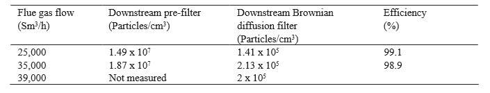
Table 5. Filter performance at start up (December 2016).
An overall efficiency of 99 % is confirmed for the particles > 20 nm. As the candles are new and not saturated with aerosols, a higher efficiency than measured during the pilot test is confirmed (Pilot test efficiency: 98 %). The efficiency is slightly decreasing at higher flue gas flow
8. Results from ELPI+ measurements in August 2017
8.1 Aerosols size distribution of the RFCC flue gas before filtration
Figure 7 shows that for all samplings, the size distribution of the RFCC flue gas before filtration is similar in the range from 0.06 to 0.2 µm. The variation of size under 0.06 µm is caused by the operation at the refinery as well as the ELPI+ sampling system, i.e. the number of small aerosols is varying with dilution effect, algorithm for small particle correction or unstable conditions. Above 0.2 µm, the particle size is increasing quickly with steam injection and temperature control of the flue gas. In addition, the ELPI+ algorithm for small particle correction removes most of the particles detected by the ELPI+.
The mass of aerosols in one cubic of flue gas could be assessed based on the ELPI+ measurements considering:
- The number of particles and size distribution.
- Spherical particles with 1000 kg/m3 as density.
Based on ELPI+ measurements, the mass concentration of aerosols is estimated at 20 mg/Sm3 by taking into account small particle correction and 500 mg/Sm3 without small particle correction. These values are much lower than the actual mass captured by the candles. In August 2017, the average mass concentration captured was 1600 mg/Sm3. A typical size distribution of 1600 mg/Sm3 is shown in the figure 7 and addition of 45,000 particles/cm3 above 1 µm is sufficient to simulate the missing weight. This number is negligible compared to the total number of particle measured (1.5 x 10⁷ particles/cm3).
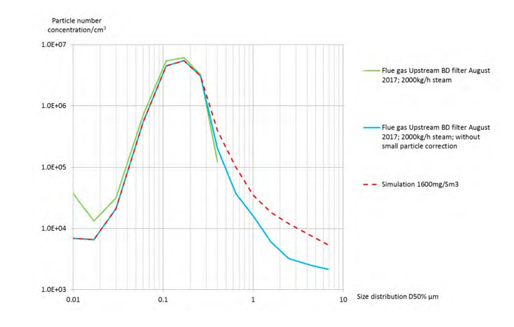
Figure 7. Summary of the measurements of the size distribution upstream the Brownian diffusion candles.
8.2 Particle number concentration of the RFCC flue gas after filtration
As summarized in tables 6, 7 and 8 in order to confirm the filter efficiency, the same test procedure for the ELPI+ measurements as in December 2016 was repeated in August 2017. The bypass of the filter and the impact to the aerosol concentration are also evaluated.
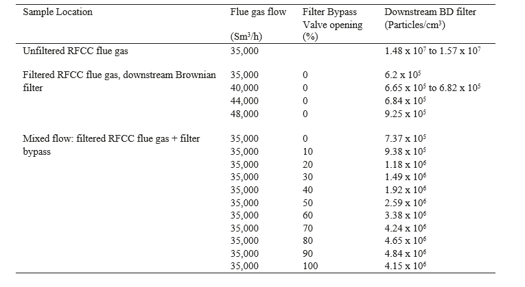
Table 6. ELPI+ measurements in August 2017 with DB filter bypass in operation. The lower particle number at 100 % opening of the bypass is likely caused by the position of the disk of the butterfly valve and a higher pressure drop.
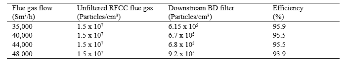
Table 7. Filter performance in August 2017
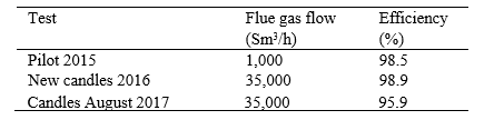
Table 8. Comparison of the filter performance to previously measured efficiencies
Comments to the efficiency results:
- The stability of the ELPI+ measurements at the BD filter inlet is challenging and variable.
- The inlet concentration is not checked simultaneously with the outlet concentration. The number of particles of the unfiltered RFCC flue gas is assumed based on previous measurements.
- The mass of particles at the filter inlet is highly variable with the steam injection and the number of particles is variable with the refinery operation. Any effect of the steam injection has not been studied.
A lower efficiency after a period of operation with RFCC flue gas is experienced and may be caused by:
- Higher water load to the candles (steam injection and variable efficiency of the demister)
- Progressive accumulation of sulfuric acid in the new candles. The accumulation is normally stabilized by drainage of the candles after several weeks of operation.
- Candles partially blocked by catalyst particles or non-soluble salts: the accumulation is confirmed by inspections, but does not look significant.
- An inspection performed in 2018 confirms that a leakage occurs in the upper part of the bed for some candles. Due to gas flow, operating conditions being above the maximum design rate and the filters being overloaded with liquid being carried over from the lower demister, the fiber beds have compressed. Further tests shall be performed in 2018 after repair the fiber beds.
- Further measurements and periodic inspections are necessary in order to estimate the life span of the candle fibers and confirm the efficiency.
9. Capacity of the BD filter bypass
The purpose of the BD filter bypass, see figures 1 and 4, is to control the aerosol concentration to the absorber in order to test the robustness of solvents for the limitation of emissions. As the flow to the DB filter bypass is not proportional to the valve opening, flue gas flow to the bypass is estimated. Methodology of the calculation is as follow:
- The total flow to the bypass and the filter is measured and controlled by the fan velocity
- At constant temperature and flue gas composition the gas flow rate to the filter is proportional to the pressure drop of the candles. Thus, the flow to the candles can be based on the candle pressure drop.
- The pressure drop of the candles has been verified at various flue gas flows
- The flow to the bypass is estimated based on the total flow and on the flow to the candles
Several tests are performed. The figure 8 describes the average gas flow to the bypass at various bypass valve opening.
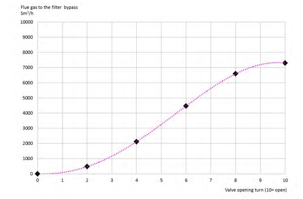
Figure 8. Flue gas flow to the bypass as a function of the butterfly valve opening. The dotted line is a polynomial trend of the test results.
As expected and confirmed by the figure 9, for aerosols under 1µm of diameter, the total particle concentration is proportional to the bypass flow. Several ELPI+ measurements are performed in order to confirm the reliability of the particle concentration in the flue gas upstream the absorber as a function of the flue gas flow to the bypass.
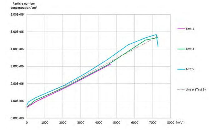
Figure 9. Flue gas flow to the bypass as a function of the particle number concentration.
Figure 10 shows a constant size distribution of the aerosols downstream the BD filter in the most of range measured by the ELPI+. No particles above 0.5 µm are measured. Without small particle correction, even if the number of large particle is overestimated, the number of particles above 0.5 µm is not significant (<1000).
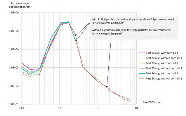
Figure 10. Particle size distribution downstream the BD filter without bypass
As shown in figure 11, the size distribution of the RFCC flue gas downstream the BD filter and after the open bypass is similar in most of the ranges measured by the ELPI+, but the particle number concentration increases with the valve opening. With small particle correction, no particles above 0.4 µm are measured. Without small particle correction, the number of particles above 0.4 µm is significant (>10,000). Consequently, the number of particles above 0.4 µm cannot be confirmed. At higher flue gas flow to the bypass, it is possible that a higher number of the larger particles are entrained to the bypass.
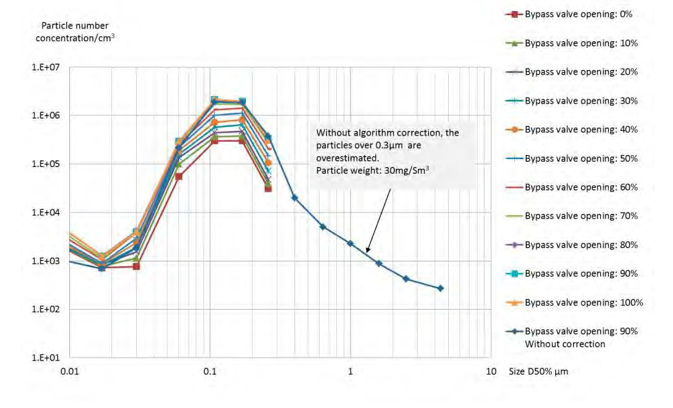
Figure 11. Particle size distribution downstream the BD filter with bypass.
10. Conclusion
The efficiency of the BD filter system installed at TCM allows the operation of the amine absorber with the RFCC flue gas without breaching the TCM amine emission permit. With the BD filter bypass, various particle concentrations may be generated and controlled in order to test the sensibility of the amine solvents to the aerosols. The test flexibility of the Technology Centre Mongstad is increased, allowing the simulation of different flue gas compositions with aerosols. During a test campaign, the efficiency of the filter is stable, even with fluctuations of the flue gas composition and the presence of components like SO2. Furthers tests are necessary in order to confirm the following items:
- Effect of the accumulation of catalyst particles in the BD filter
- Effect of high and variable aerosol mass to the BD filter
- Estimate the life span of the candles
- Demister efficiency
The removal of aerosols and fly ash in a flue gas is usually and preferably performed by electrostatic precipitators (ESP) and fabric filters, but the tests at TCM suggest that a BD filter may be applicable in specific full scale projects. The BD filter may be installed upstream or downstream of the absorber if the fly ash concentration is minimized upstream of the BD filter as achieved at TCM.
The ELPI+ (Electrical low pressure impactor) is reliable to measure the aerosol number concentration. However, in the specific case of aerosols above 2 µm diameter composed only of water, the ELPI+ is not applicable since these aerosols are unstable and easy to evaporate. An assessment of the accuracy of the correction algorithm for the fine particles used to correct the ELPI+ readings may be necessary, especially for aerosols above 1 µm of diameter in a flue gas.
11. Acknowledgements
The authors gratefully acknowledge the staff at TCM DA, Gassnova, Equinor, Shell and Total for their contribution and work at the TCM DA facility. The authors also gratefully acknowledge TCM owners and the Climit Demo project AeroSolve (616125) for their financial support and contributions.
References
- The open-source centre at TCM. https//catchingourfuture.com/
- Lombardo G, Fostås BF, Shah MI, Morken AK, Hvidsten OA, Mertens J, Hamborg ES. Results from aerosol measurement in amine plant treating gas turbine and Residue Fluidized Catalytic Cracker flue gases at the CO2 Technology Centre Mongstad. Energy Procedia. Volume 114; 2017. p. 1210-1230.
- Shah MI, Lombardo G, Fostås BF, Benquet C, Morken AK. CO2 capture from RFCC flue gas with 30 wt% MEA at Technology Centre Mongstad, process optimization and performance comparison. (to be presented at GHGT-14, 2018, Melbourne, Autralia)
- Mertens J, Lepaumier H, Desagher D, Thielens ML. Understanding Ethanolamine (MEA) and ammonia emissions from amine based post- combustion carbon capture: lessons learned from field tests. Internat. J. Greenhouse Gas Control. 2013, 13, 72-77.
- Mertens J, Brachert L, Desagher D, Thielens ML, Khakharia P, Goetheer E, Schaber K. ELPI+ measurements of aerosol growth in an amine absorption column. Internat. J. Greenhouse Gas Control. 2014, 23, 44-50.