
4. Controlling amine mist formation in CO2 capture from Residual Catalytic Cracker (RCC) flue gas (2014)
Otto Morten Bade*, Jacob Nygaard Knudsen, Oddvar Gorset, Inga Askestad
Aker Solutions, PO Box 222, NO-1326 Lysaker, Norway *Corresponding author

(http://creativecommons.org/licenses/by-nc-nd/3.0/).
Peer-review under responsibility of the Organizing Committee of GHGT-12
doi: 10.1016/j.egypro.2014.11.098
Abstract

Aker Solutions has developed a novel emission control system involving the combination of anti-mist design and an acid wash polishing step. This concept was tested at a 200 kg/h CO2 Mobile Test Unit (MTU) operating on flue gas from a Residual Catalytic Cracker (RCC). It was found that the RCC gas contained relatively high concentration of H2SO4 mist (up to 33 mg/Nm3) compared to what is typically seen from a modern coal-fired power station. The high concentration of H2SO4 nuclei generated high amine emission (>200 ppm) when the MTU was operated in conventional mode. On the other hand when the MTU was operated in anti-mist mode the emissions were greatly reduced and amine emissions down to 2 ppm were confirmed by manual emission measurements. A test with conventional mist abatement technology (Brownian diffusion filter) installed upstream the MTU was also performed. It was shown that the filter had large removal efficiency of H2SO4, however still significant amine emissions persisted when the MTU was not operated in anti-mist mode. The results clearly demonstrate that the Aker Solutions’ Anti-Mist design is an attractive option for mist abatement compared to conventional technology.
1. Introduction
In recent years the focus on potential emission of amines and amine degradation production from post combustion capture (PCC) plants has increased substantially. In particular emissions of amines and harmful degradation products such as nitrosamines and nitramines are a concern. Direct emissions of nitrosamines and nitramines can largely be avoided by selecting amine solvents that do not form stable nitrosamines and nitramines at the conditions prevailing in the capture process. However, emission of compounds containing amine groups are still a concern as these compounds may undergo nitrosation in the atmosphere to form nitrosamines or nitramines. For this reason it has been a key priority for Aker Solutions to develop emission control technology that can secure low emissions of amines to the environment. Amines and other degradation products may in principle be emitted from post combustion plants by three different mechanisms: Gas phase emission, entrainment of liquid droplets as well as mist (aerosol) formation. Where conventional emission control technologies such as water wash sections and demisters have been an integral part of the design of amine based CO2 capture plants for years, typically no abatement technologies have been implemented to deal with amine mist. Amine mist may be formed in the CO2 absorber when vapor phase amine is absorbed in fine mode water droplets (mist). Because of the tiny particle size of the mist particles they tend to penetrate wash sections and conventional demisters. Thus, there is a risk that the conventional emission control technologies may not be sufficient to meet the stringent emission limits that are likely to be imposed on large-scale PCC plants.
In a previous work [1], the Aker Solutions’ Mobile Test Unit (MTU) was located at Southern Company’s Ernest
C. Gaston Electric Generating Plant/National Carbon Capture Center (NCCC) in Wilsonville, Alabama, USA. The MTU was operated on flue gas from unit 5, a modern coal-fired boiler equipped with DeNOx, ESP and wet FGD. The MTU is equipped with Aker Solutions’ novel emission control system, which consists of a novel absorber design to prevent amine mist formation and a final pH-controlled wash stage to eliminate emissions of volatile alkaline compounds. The tests showed that significant emissions of solvent amines in the form of mist may occur with conventional emission control technology. However, the formation and emission of amine mist could nearly be eliminated with Aker Solutions’ Anti-Mist design. In addition, the tests showed large removal of volatile compounds like ammonia and alkyl amines. Thus, all in all the tests indicated that Aker Solutions’ novel emission control concept could virtually eliminate emissions of amines and other alkaline constituents when treating flue gas from a typical coal fired power plant.
In this work, a test campaign with flue gas from the Residual Catalytic Cracker (RCC) at Mongstad Refinery has been conducted at the Aker Solutions’ Mobile Test Unit. The aim was to test Aker Solutions’ Anti-Mist system on the RCC gas. The work was done in cooperation with TCM DA. The campaign included a test with a Brownian Diffusion (BD) filter temporary installed on the flue gas supply line upstream of the MTU. The filter was installed and operated by TCM DA. The tests were performed with one of Aker Solutions’ advanced amine solvents.

2. Test facility and Test Program
2.1 Mobile Test Unit
All the test results reported in this paper are based on test campaigns conducted at Aker Solutions’ Mobile Test Unit (MTU). The MTU is a custom-built mobile test CO2 capture facility, which can be used to capture CO2 from different industrial flue gases. The facility is used to verify new design features and solvents, and operates in an industrial environment during long-term testing. The facility is designed for easy transport and hook-up, which means that it can be transported to different sites.
The MTU was first commissioned in 2008 and since then several test campaigns have been conducted at different test locations and with different solvents [2, 3]. Amongst others verification of emission control technology and emissions has been an area of attention [2, 3]. Process improvements and new technology have been implemented in the MTU on a continuing basis.
A picture of the MTU is shown in Figure 1. The MTU was located at CO2 Technology Centre Mongstad in the period June 2012 to March 2014. The design of the MTU is based on conventional amine absorption/desorption process with full packing height absorber and desorber columns. Several novel features are installed such as Aker Solutions’ Energy Saver and proprietary emission control technology. The MTU absorber is fitted with two pump- around water wash sections in series. An acid wash is located above the two water wash sections. Extensive instrumentation is implemented at the MTU and all on-line signals are logged in historical databases.
During 2011and 2012 the MTU was modified to include Aker Solutions’ Anti-Mist Design to significantly reduce emissions of amine mist. Key design data and specifications of the MTU are shown in Table 1.
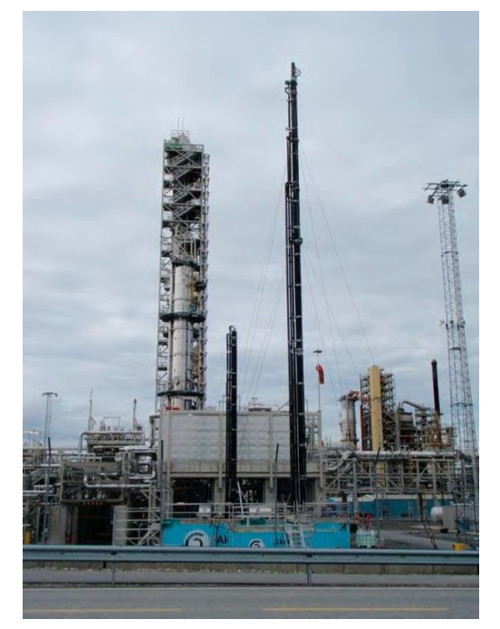
Figure 1. Picture of the MTU (Blue container with absorber and stripper tower in front of the TCM DA Amine Plant at Mongstad).
The MTU is equipped with a permanent FTIR online emission monitoring system from GasmetTM. The FTIR is connected via heated sampling lines (180°C) to sampling probes at the absorber inlet (downstream DCC), absorber outlet and desorber overhead condenser outlet. The FTIR is calibrated for a list of standard flue gas pollutants, e.g. CO, CO2, SO2, HCl, NO, NO2, NH3, as well as MEA and Aker Solutions’ solvent amines.
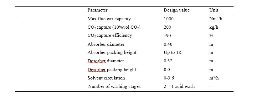
Table 1. MTU Key design data and specifications
2.2 Test program
For the tests reported in this paper the MTU was located at CO2 Technology Centre Mongstad (TCM DA), Norway. The MTU was operated on flue gas from the RCC unit at the Statoil Mongstad Refinery. The RCC unit is equipped with SNCR, dry ESP and seawater FGD. Off gas from a Sulfur Recovery Unit is mixed into the RCC flue gas upstream of the Seawater FGD. The combined RCC and SRU gas is quenched from approx. 300 °C to approx. 25 °C in the FGD. Flue gas to the MTU was extracted from the FGD outlet duct. Between tie in on FGD and MTU, the flue gas path contains a booster fan, a cyclone for particulates removal, a DCC for temperature control. There is no pH control on the DCC. The flue gas entering the MTU is water saturated with a temperature of approx. 25 °C and contains approx. 14% CO2, 20-60 ppm SOx, approx. 80 ppm NOx and traces of RCC catalyst fines.
Inside the MTU unit, there is another DCC with pH control and caustic dosing. The SO2 content into the MTU amine absorber is typically 0- 2 ppm.
Data is reported from a MTU test campaign conducted in the period May – October 2013. The scope of the test campaign was to test Aker Solutions’ novel emission control system for mist abatement on flue gas containing sulfuric acid aerosols and acidic catalyst fines. The MTU is equipped with Aker Solutions’ Anti-Mist design. The Aker Solutions’ Anti-Mist design is patent pending.
2.3 Test procedures
The anti-mist design in the MTU has been implemented in a flexible way that allows switching between conventional mode and anti-mist mode operation within a time frame of say 15-60 minutes. In this way it has been possible to directly demonstrate the benefits of the anti-mist design on amine emissions.
Prior to switching from conventional to anti-mist mode operation and vice-versa, the MTU was held in steady state operation. This means that the main operational parameters such as capture rate, reboiler temperature, desorber pressure, flue gas and solvent flow rates were maintained at fixed values. The MTU was operated with two water wash stages during the entire campaign. During the entire test campaign the emissions of amine from the absorber were monitored by the online FTIR system.
In order to differentiate between vapor phase and mist phase emission, the acid wash section located above the two water wash sections was set in operation in periods during the test campaign. The acid section is known to efficiently absorb vapor form alkaline compounds such as amines and ammonia. No cooling was applied in the acid wash system in order to avoid condensation of water from the flue gas and thereby bleeding of acid wash water. The acid dosing is based on pH control.
As a conventional alternative to anti-mist operation, a Brownian Diffusion (BD) filter was temporary installed inline on the flue gas supply line to the MTU. The aim was to operate the MTU in “conventional mode” (not anti-mist mode) and investigate the performance of the BD filter with respect to mist formation in the MTU absorber. Testing of the BD filter was done in cooperation with TCM DA. The filter was hired by TCM DA from Begg Cousland Envirotec Limited. The BD pilot rig (Figure 2) consists of a wetted rotating brush, followed a Brownian Diffusion type candle filter installed inside a vertical vessel. Water spin off from the brush and water coming from mist coalescing inside or at the inner surface of the fabric candle is collected at the bottom of the vessel and drained out. The BD filter was assembled and operated according to instructions given by the supplier.
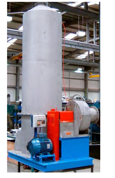
Figure 2: Brownian Diffusion (BD) filter.
Online FTIR emission monitoring: The MTU’s permanent FTIR system was used for online monitoring of amine emissions from the absorber during both test campaigns. The FTIR technique has the advantage that the sample gas is measured at actual conditions without any preconditioning, hence reducing the risk of analyte loss. To avoid condensation of water in the sampling system and the analyser, the FTIR gas cell and the sampling lines are heated to 180°C. This also has the advantage that any target compounds that is present as mist or droplets will be evaporated and analysed. Hence, the FTIR monitor provides the total content of the different analytes in the flue gas. The experience from the MTU is that reliable NH3 and amine readings down to approximately 1 ppmv can be obtained.
Manual emission measurements: Manual emission measurements were conducted at the outlet of the MTU absorber (stack) during stable operation to quantify the amine emissions and hence verify the FTIR readings. A sampling train consisting of a short unheated isokinetic probe connected to 4 impingers in series was applied. The impingers were filled with 0.05 M sulfuric acid as absorbent and placed in an ice bath. Flue gas was isokinetically drawn through the impingers and a silica gel dryer by the means of a gas tight pump. A gas meter was used to quantify the sampled amount of flue gas. The whole sampling system is provided by Paul Goethe GmbH in Germany. Each measurement lasted for 1-2 hours. The impinger samples were analyzed by LC-MS.
Particulate measurements at absorber inlet: Particulate measurements according to EPA method 5 were conducted on the absorber inlet, both with and without the Brownian diffusion filter installed. Isokinetic sampling was performed with probe and filter holder heated to 90 °C, in order to avoid any condensation of water but at the same time avoid loss of sulfuric acid due to vapor phase break through. The filters were pre-dried overnight in a desiccator prior to sampling, and immediately placed in desiccator after sampling until weighing was done. Total amount of particulates were determined gravimetrically. The filters were extracted in demineralized water, which was analyzed for anions and cations by IC.
3. Results and Discussion
3.1 Reducing mist borne amine emissions through Aker Solutions’ novel Anti-Mist design
With conventional operation (i.e. no anti-mist operation) on the RCC flue gas, massive amine mist formation was seen as a dense plume from the absorber stack and as high amine recordings on the online FTIR. Hence very little conventional operation was conducted, as the permit to operate was limited to a total amine emission below 6 ppm on a 24 hour basis. Some short duration attempts with conventional operation were performed, and amine spikes sometimes above 200 ppm were recorded by the FTIR.
During the MTU anti-mist operation on RCC gas in September 2013, the FTIR indicated total amine emissions
in the range 1-4 ppm. The high emission spike on 25th of September as shown in Figure 3 was due to a test, where the anti-mist system was switched off for 30 minutes. The FTIR recorded an amine spike of >200 ppm. The flue gas flow rate of 400 Sm3/h and capture rate of approx. 90% was not changed. The acid wash section was not in service.
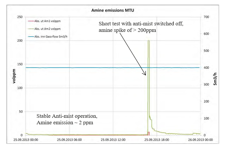
Figure 3. Emission of solvent amines during operation alternating between conventional and anti-mist mode.
In another test, with stable anti-mist operation and few ppm emission of amine, the acid wash was tested for some time in order to distinguish between mist phase emission and gas phase emission. The acid wash removes volatile alkaline compound but not mist borne emission. It was observed that ammonia emission was reduced to very low levels while amine emission dropped only marginally, indicating that mist borne amine emission is far more significant compared to gas phase emission of amines.
3.2 Results from particulate measurements and test with flue gas pre-cleaning using Brownian diffusion (BD) filter
Particulates measurements were performed on the flue gas entering the MTU. The amount of particulates were determined gravimetrically. The total amount of collected material was approximately 30 mg/Nm3. The filter samples were extracted in water and analysed for ions. The results showed that most of the collected mas consisted of sulphate anions. It is also anticipated that a fraction of the total collected mass consists of RCC catalyst fines.
Tests in October 2013 were conducted with a Brownian diffusion (BD) filter installed upstream the MTU. The aim was to operate the MTU in “conventional mode” (not anti-mist mode) and investigate the performance of the filter with respect to mist formation in the MTU absorber. The BD filter is known to be efficient for removal of sub- micron particulates. By removing the mist nuclei upstream of the CO2 absorber, the amine mist formation within the absorber should be avoided.
Indeed, particulate measurements performed on flue gas upstream of the absorber confirmed proper efficiency of the BD filter unit. The amount of particulates collected dropped from approximately 30 mg/Nm3 to less than 1 mg/Nm3.
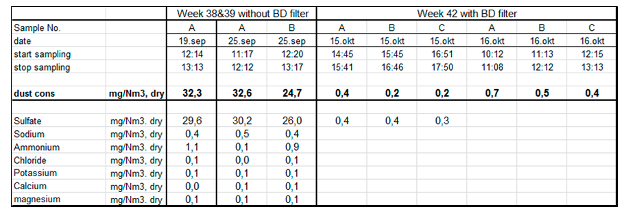
Table 2: Results from dust measurements at MTU absorber inlet. Total “dust” collected and IC analysis on filter catch.
3.3 Results from Manual amine emission measurements
Results from isokinetic measurements are presented in Table 3. The reported figures are from a measurement performed during stable anti-mist operation (without BD Filer) on the 25th of September 2013 and from a measurement performed during stable conventional operation (without anti-mist) but with BD filter installed upstream MTU.
The total amine emission with anti-mist operation was 2.1 ppm, without the BD filter installed. This compared to
7.6 ppm for the test with BD filter treatment on flue gas, but with conventional operation (no anti-mist) of the amine plant. So although the BD filter had large removal efficiency of H2SO4 mist, still higher amine emissions persisted when the plant was not operated in anti-mist mode. The MTU was also operated with anti-mist and with BD filter in place, but unfortunately no manual emission measurement was performed for this case. The FTIR indeed showed low emission.
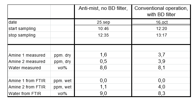
Table 3: Results from isokinetic emission measurements at MTU absorber stack. The corresponding FTIR readings are reported for comparison.
The results clearly demonstrate that the Aker Solutions’ anti-mist design is an attractive option for mist abatement compared to conventional technology, such as flue gas pre-cleaning with Brownian Diffusion (BD) filter or wet ESP. The BD filter has significant pressure drop and potentially a large maintenance cost due to filter clogging over long time operation. Regarding the anti-mist design, there is no increased operating cost of the plant, and there is no loss of performance. It is anticipated that anti-mist operation avoids amine mist formation, and that the residual emission of approx. 2 ppm may stem from amine chemically absorbed on acidic RCC catalyst fines or sulphuric acid fumes that passes through the absorber.
In previous test campaigns at TCM DA, the MTU was operated on flue gas from the natural gas fired Combined Heat and Power (CHP) plant at Mongstad. Emission measurements under that conditions showed ultra-low amine emissions (<0.01 ppm) with Aker Solutions’ full emission control concept. Compared to the RCC gas, the CHP flue gas is very clean and contains very low amounts of particulate matter including H2SO4 nuclei. Thus, mist formation is not a significant mechanism for amine emission during operation with CHP gas. The MTU tests on different industrial flue gas sources clearly illustrate that the lower amine emissions can be achieved on the flue gas sources with the higher purity.
3.4 Challenges related to emission measurements
Manual sampling: It is known that sampling of mist/aerosols in impingers is challenging due to risk of poor capture rate of the aerosols. The analytical results showed however good ratio of analyte concentration between the impingers. For the test performed with anti-mist operation on the 25th of September, the distribution of amine in the impingers No. 1 to 4 were 94%, 4%, 1% and 1 %, respectively. For the BD filter test without anti-mist operation of the 16th of October, the amine distribution was even better with 99% of the analyte was collected in impinger 1.
FTIR: An operational challenge was that the FTIR intake filter and microfilter upstream FTIR cell quickly became contaminated with RCC catalyst dust. Only few days in operation with new filters showed an increased memory effect (amine and ammonia responses becomes slower). It was also observed that the catalyst dust “cracks” the amine1 to NH3. When provoking mist emission by running short duration conventional operation, a spike of ammonia was seen, while am1 emission was lower than expected. Ammonia is not prone to follow mist, so this increased ammonia emission was ascribed breakdown of amine 1 and formation of ammonia in the FTIR sampling system. This explains why amine 1 is not seen on the FTIR during the manual emission measurements. A large improvement on response and ability to measure amine 1 is seen immediately after filter replacement. Aker has not observed this sort of FTIR issue on earlier sites with coal fired flue gas, meaning that the RCC dust probably creates some specific challenges for the online emission monitoring. On previous sites, the filters were usually replaced once a year. Note that the Gasmet FTIR sampling system operates at 180 °C.
4. Conclusion
The Aker Solution’s MTU was operated on flue gas from a Residual Catalytic Cracker (RCC) at Technology Centre Mongstad, Norway. Due to relatively high acid mist concentration in the RCC flue gas, conventional operation of the MTU yielded high amine emission in the form of mist. Amine emissions were reduced with approximately two-orders of magnitude with anti-mist design. In additional, the anti-mist design resulted in lower amine emissions that could be achieved with a BD filter installed. The results clearly demonstrate that the Aker Solutions’ anti-mist design is an attractive option for mist abatement compared to conventional technology.
Acknowledgements
This work has been performed as part of the SOLVit project phase 3. The SOLVit project phase 3 is sponsored through the strategic Norwegian research program CLIMIT. The authors would like to express their gratitude to the sponsors and partners in the program. Also the authors acknowledge the staff at TCM DA for their cooperation and support with the test campaigns.
References
- J.N. Knudsen, O. M. Bade, M. Anheden, R. Bjorklund, O. Gorset, S. Woodhouse: Novel Concept for Emission Control in Post Combustion Capture. Energy Procedia, Vol. 37 (2013), pp. 1804–1813 [1]
- Oscar F. Graff and Vibeke Andersson. Staged Development of Carbon Capture Technology. CLIMIT Conference, 12-13 October 2010, Oslo, Oscar F. Graff. Emission measurement Norway.
- Oscar F. Graff. Emission measurement and analysis from Mobile Carbon Capture Test Facility. IEAGHG Conference Environmental Impacts of Amine Emission During Post Combustion Capture. 16 February 2010, Oslo, Norway.