
5. CESAR1 Solvent degradation and thermal reclaiming results from TCM testing (2022)
Matthew Campbella, Sundus Akhtera, Anette Knarvika,b, Muhammad Zeeshana, Ahmad Wakaaa
aTechnology Centre Mongstad, 5954 Mongstad, Norway
bEquinor ASA, PO Box 8500, 4035 Stavanger, Norway
Abstract
The Technology Centre Mongstad (TCM DA) in Norway has investigated degradation and amine losses for the non- proprietary solvent CESAR1 which is a mixture of water, amino-2-methylpropanol (AMP) and piperazine (PZ). Results have been explored during the ALIGN CCUS testing campaign which utilized the combined cycle gas turbine (CCGT) based heat and power plant (CHP) flue gas with an inlet CO2 concentration around 3.7 vol%. It has been demonstrated that there is a significant impact on amine losses through degradation when the inlet NO2 concentration entering the CO2 absorber is increased. The increase in NO2 concentration in the flue gas resulted from Selective Catalytic Reduction (SCR) operation with no ammonia injection. Degradation results have also been shared for the residue fluid catalytic cracker (RFCC) flue gas from the Equinor refinery with an inlet CO2 concentration around 13.5 vol%. Due to the impurities in the RFCC flue gas higher amine losses through degradation are observed compared to CHP flue gas testing. Also, amine losses through degradation for CESAR1 solvent were compared against historical TCM results for monoethanolamine (MEA). The results indicate significantly lower amine losses for CESAR1 as compared to MEA for both CHP and RFCC flue gases. Thermal reclaiming has also been performed on the aged CESAR1 solvent and effective operation was achieved with acceptably low amine losses during semi-continuous reclaiming operation. Future testing at TCM in the laboratory and full-scale plant are planned to have a better understanding of the major causes for amine solvent degradation.
Keywords: CESAR1, MEA, Degradation, Thermal Reclamation
1. Introduction
In 2019 and 2020 Technology Centre Mongstad (TCM) experimentally explored the behavior of the CESAR1 amine-based solvent for post combustion CO2 capture. The main purpose of the testing campaigns was to generate results needed to evaluate CESAR1 performance in comparison to the current industry non-proprietary amine based solvent benchmark, which is monoethanolamine (MEA). The main areas of investigation were:
- CO2 capture rate
- Specific reboiler duty (SRD)
- Emissions
- HSE and Operational challenges
- Solvent degradation products and rate
- Thermal reclaiming operation
This paper focuses on summarizing degradation results for a natural gas-fired combined heat and power (CHP) plant (flue gas composition ~ 3.7 vol% CO2 and ~ 14% O2) and for the refinery residue fluid catalytic cracker (RFCC) plant (flue gas composition ~ 13.5 vol% CO2 and ~ 3.2% O2). Also, a summary of CESAR1 thermal reclaiming results will be presented. This article will be divided into the following sections:
- CESAR1 degradation reaction mechanisms
- CESAR1 degradation results and rates
- Degradation comparison for CESAR1 versus TCM historical MEA
- Overview of CESAR1 thermal reclaiming
- Way forward to gain a better understanding on solvent degradation.
2. CESAR1 degradation mechanisms
Although the degradation products from a mixture of 2-amino-2-methyl-1-propanol (AMP) and piperazine (PZ) have not been explored thoroughly, several studies have been carried out in literature to propose and evaluate the degradation mechanism of PZ and AMP separately. In this section, the mechanisms for the degradation of different degradation products will be discussed.
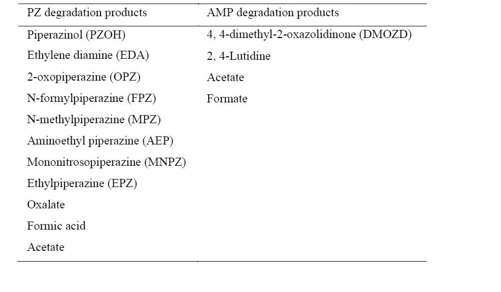
The main areas of degradation for any amine in post-combustion CO2 capture process are the absorber sump, cross heat exchanger, reboiler, and reclaimer [1]. Thermal degradation which occurs mainly due to the high temperature of the process, and oxidative degradation because of the presence of dissolved oxygen and free radicals [1]. The major PZ and AMP degradation products are listed below in Table 1.
2.1 Overview of PZ Thermal Degradation
The PZ molecule has the tendency to absorb two molecules of CO2 per mole of piperazine due to the presence of two amino functional groups present in a cyclic structure. The degradation pathway of PZ solvent is not completely established for each degradation product, but the mechanism for the major degradation products of PZ have been suggested [1, 3-5]. Reactions such as bimolecular nucleophilic substitution reaction (SN2), elimination, urea generation and hydrogen-abstraction are involved in the degradation pathway [1]. Iron may also affect the formation of total formate and ammonia as both increase with increase in iron concentration, suggesting that the dissolved iron might be responsible (catalyse) for the decomposition of the intermediary oxidation products to formate and ammonia [2]. Most abundant thermal degradation products are FPZ, EDA, AEP, formate and ammonia [3]. The mechanism for the thermal degradation of PZ is shown in Fig. 1.
In the first step, PZ acts as a nucleophile at the α-carbon of another molecule of a protonated PZ (P+) in SN2 reaction to give 1-(2-aminoethyl)-ethylpiperazine (AEAEPZ) as shown in Fig. 1. AEAEPZ has the tendency to get protonated at multiple positions due to the presence of nucleophilic primary, secondary and tertiary amino functionalities (Fig. 1 to Fig. 3). In the case of protonation of the inner-secondary amine group between C4 and C5, PZ can attack at the α-carbons (C4 and C5) to yield 1- polyethylpiperazine (PEP), protonated ethylene diamine (EDA+) and two molecules of 1-(2-aminoethyl)piperazine (AEP) respectively. If the tertiary nitrogen in the AEP molecule is protonated, then the α-carbon becomes prone to an SN2 reaction with another molecule of AEP nucleophile resulting in 1,4-diaminoethylpiperazine (DAEP) and AEP+. On the other hand, AEAEPZ can react rapidly in the presence of CO2 in the solution to form internal urea. The internal urea, when protonated, can give a substitution reaction with another molecule of PZ which attacks on the C6 of this internal urea under SN2 reaction yielding other degradation products such as ammonium, CO2 and quaternary amine. Similarly, EDA can also react with CO2 to form imidazolidinone. AEP can also get protonated at multiple positions. If the protonation occurs at the terminal amine, the C7 can be approached by another molecule of AEP to yield polyAEP and ammonium while the protonation at the tertiary nitrogen gives DAEP and PZ+, as shown in Fig. 1.
PEP in its protonated form (at one of the tertiary amines in the cyclic structure) can undergo Hofmann’s elimination reaction to give 1-ethenylpiperazine and PZ. The elimination reaction is facilitated by higher temperatures and a mix of nucleophiles present in the solution. PEP can undergo Anti-Markovnikov hydration of 1-ethenylpiperazine in the presence of water to form 2-Hydroxyethylpiperazine (HEP) [1, 3-4]
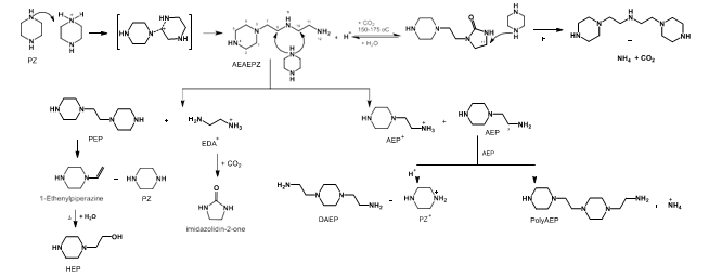
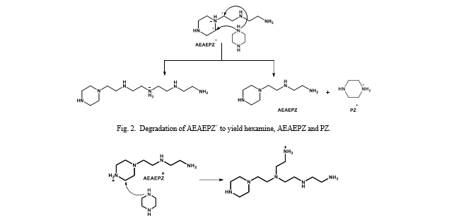
If the tertiary amine of AEAEPZ gets protonated, it can react with a PZ molecule at positions C7 and C1 to yield hexamine and a molecule of AEAEPZ and PZ+ respectively (Fig.2). Similarly, protonation of the amino group in the cyclic structure of the AEAEPZ molecule followed by an attack of PZ nucleophile at C2 can give rise to the long chain hexamine shown in Fig. 3.
2.2 Overview of PZ Oxidative Degradation
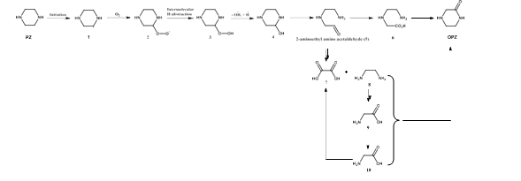
The first step in the oxidative degradation pathway is the formation of peroxide radicals. The process starts with the abstraction of a proton from one of the methylene carbon in PZ molecule thus forming a free radical which can form peroxyl radical in the presence of O2. Degradation of the peroxyl radical may take place through; 1)intermolecular abstraction of proton (Fig. 4) or 2)intramolecular abstraction of proton (Fig. 5).
In the event of intermolecular abstraction of protons in an alkaline medium, peroxide (2) is generated together with •OH and •H. In the next step 2-hydroxyl-PZ (3) is formed, further oxidation results in the generation of (4). The [(2- aminoethyl) amino]acetaldehyde (5) undergoes further oxidization to give oxalic acid (7) and EDA (8). EDA can further degrade to give glycine (9) and glycolic acid (10). In a complex series of reactions oxalic acid and EDA can react to form 2-oxopiperazine (OPZ). The aldehyde (5) can also oxidize to give carboxylic acid (6) which undergoes ring closure reaction to give OPZ, as shown in (Fig. 4) [6-8].
Intramolecular proton abstraction may take place resulting in the peroxide radical which in the presence of •OH and through a homolytic cleavage of C2 ̶ C3 bond yields imine (11). Compound (11) degrades further to give unstable [(2-aminoethyl)amino}acetaldehyde] (12) and formaldehyde (13). Further degradation of (12) can form EDA (8) and formaldehyde. Formaldehyde undergoes oxidation to give formic acid (14) which in the presence of PZ can yield FPZ, see Fig. 5 [6- 8]
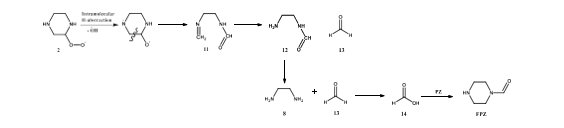
In other products, acetate and PZ can also react together to form acetyl piperazine (APZ), whereas, reaction of piperazine in the presence of CO2 gives piperazine carbamate, which undergoes nitrosation in the presence of nitrite to give 1-nitrosopiperazine (MNPZ), see Fig. 6 [9,10]
2.3 Overview of AMP Thermal Degradation
The main thermal degradation product of AMP is DMOZD. It is formed by the reaction of AMP with CO2 to form AMP-carbamate which is unstable and undergoes cyclisation and dehydration to yield the oxazolidinone DMOZD, see Fig. 7. Since AMP is branched and sterically hindered, it is less prone to further secondary degradation reactions compared with MEA. Thus, it is limiting the secondary degradation products formation. According to Gouedard et al. [11], some other thermal degradation products include 2,2-trimethylethanolamine, 4,4-trimethyloxazolidin-2-one, 4,4- dimethyl-1- hydroxytertiobutylimidazolidin-2-one, and l,3-bis(2-hydroxy-l,ldimethylethyl)urea [11,12].
![Fig. 7. AMP thermal degradation pathway through carbamate formation, followed by cyclization and dehydration to 4,4-dimethyl-1,3-oxazolidin- 2-one (DMOZD) [11].](https://gassnova.no/app/uploads/sites/5/2022/04/1-39.png)
2.4 Overview of AMP Oxidative Degradation
The mechanism for the oxidative degradation of AMP via peroxyl radical mechanism, is shown in Fig. 8. Wang et al. [7] proposed an intramolecular hydrogen abstraction from either NH or CH bond that resulted in imine and enamine formation. Both the imine and enamine can be degraded further to give (3) and (4) with the loss of OH radical. Hydrolysis of the enamine results in the formation of ammonia and formaldehyde. The hydrolysis of compound (4) can give secondary degradation products such as acetone, acetic acid ammonia, nitrate and nitrite etc. Another major product from oxidative degradation of AMP is 2,4-lutidine. The formation of lutidine goes through a series of reactions involving imine and formaldehyde, see Fig. 8 [7, 8]
![Fig. 8. AMP degradation pathway via peroxyl radical mechanisms adapted from Wang et al. [7,8]](https://gassnova.no/app/uploads/sites/5/2022/04/1-40.png)
3. CESAR1 degradation results and rates
The analysis of degradation rate is based on 2 testing campaigns performed, in 2019 ALIGN CCUS on CHP flue gas and in 2020 TCM Owners campaign on RFCC flue gas. More details for flue gas compositions can be found in [13]. Throughout the testing campaigns, samples were taken from lean amine and chemical analysis of the samples were performed to analyze the solvent composition. The main CESAR1 degradation products which were measured and quantified during testing are listed below. All measurements of degradation products were performed by Sintef.
- 2,4-lutidine
- DMOZD – 4,4-dimethyl-2-oxazolidinone
- MNPZ – N-methylpiperazine
- OPZ – 2-oxopiperazine
- Organic acids and heat stable salts
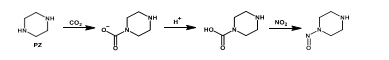
Fig. 9 demonstrates the change in degradation product concentration during the ALIGN (CHP flue gas) testing campaign. As can be seen there are 2 main zones where detailed degradation calculations and assessments have been performed.
Zone 1: Operation from September 12, 2019, to October 12, 2019, during this testing period operation the NO2 absorbed by the CESAR1 was on average 0.5 ppmv. This concentration of NO2 is considered low and was the result of constant ammonia feed to the SCR upstream of the amine plant.
Zone 2: Operation from October 12, 2019, to November 1, 2019, during this testing period operation was quite stable and the NO2 absorbed by the CESAR1 solvent was on average 2.35 ppmv. This concentration of NO2 is considered high and was the result of no ammonia feed to the SCR upstream of the amine plant. This was not a planned test, however the variation of NO2 concentration will allow a comparison of CESAR1 degradation rates with high and low NO2 concentrations.
The results clearly demonstrate an increased slope of nitrosamine formation in Zone 2, which as expected coincides with a significant increase in NO2 entering the absorber.
![Fig. 9. Degradation product concentrations in Zone 1 and Zone 2 during CESAR1 testing campaign. This figure has been presented in [14] and discussed in short.](https://gassnova.no/app/uploads/sites/5/2022/04/1-41.png)
For the 4 quantified non-volatile degradation products (DMOZD, 2,4-lutidine, MNPZ, OPZ) the total accumulation is determined for Zone 1 and Zone 2 and presented in Table 2. It should be noted that 2,4-lutidine is not included because the formation rate was observed to be zero. The rates of formation of MNPZ and OPZ have increased in Zone 2 as compared to Zone 1, due to the increased NO2 concentration. To calculate the total amine losses resulting from degradation, it is required to know the individual formation for each degradation product and to use the stoichiometric relationship with amine moles consumed. A common manner of expressing amine losses through degradation is by the following expression: Amine loss ratio = kg of amine loss/ton CO2 captured.
Table 2. Degradation products total accumulation in Zone 1 and Zone 2.
| Degradation products | Units | Zone 1 | Zone 2 |
| 4, 4-dimethyl-2-oxazolidinone (DMOZD) | kg | 38 | 19 |
| Mononitrosopiprazine (MNPZ) | kg | 40 | 158 |
| 2-oxopiperazine (OPZ) | kg | 33 | 68 |
For this calculation it is required to quantify the total amine losses through degradation and total CO2 captured in Zone 1 (low NO2) and Zone 2 (high NO2), the results are shown in Table 3. The results demonstrate that the amine loss ratio through degradation has doubled in Zone 2 as compared to Zone 1, a result of the increased NO2 concentration.
Table 3. Amine loss ratio through degradation (quantified degradation products).
| Parameter | Units | Zone 1 | Zone 2 |
| Amine loss to degradation | kg | 87 | 191 |
| CO2 captured | kg | 1971 | 2112 |
| Amine degradation loss ratio | kg/tonCO2 | 0.044 | 0.091 |
The rates of degradation above consider the quantified degradation products measured. However, it should be noted that there can be other unquantified degradation products which would contribute to additional amine loss through degradation. A way to assess if there are significant unquantified degradation products, is to observe the alkalinity or nitrogen balance for solvent samples taken during the test campaign. An assessment was done to observe how the alkalinity difference is closing for the CESAR1 solvent at different times in Zone 1 and Zone 2. This was achieved by comparing the measured solvent alkalinity versus a calculated solvent alkalinity. The measured alkalinity is based on titration results where all alkaline components (known or unknown) in the solvent will contribute to total solvent alkalinity whereas the calculated solvent alkalinity considers the solvent amines and quantified degradation products. Fig. 10 demonstrate the alkalinity difference during the testing period.
The alkalinity difference increases in Zone 2 as compared to Zone 1, where at the end of Zone 2 the alkalinity difference is around 5%. This signals that as time increases, especially with high NO2 that there are unknown or unquantified degradation products which are increasing in the CESAR1 solvent. Therefore, it can be expected that the amine loss ratios through degradation presented in Table 3 are underestimated. A revised calculation of amine loss ratio through degradation including the above alkalinity difference is shown in Table 4. The amine loss ratio in Zone 2 has increased (~ 1.85 times) from 0.091 kg amine/ton CO2 (excluding unknown degradation products) to 0.169 kg amine/ton CO2 (including estimate of unknown degradation products). There is no significant change or adjustment in Zone 1 amine loss ratio since the alkalinity difference was close to zero. Analysis performed to understand the degradation products contributing to the alkalinity difference are described in [14] and Section 6 of this article.
| Parameters | Units | Zone 1 | Zone 2 |
| Amine loss to degradation | kg | 87 | 357 |
| CO2 captured | kg | 1971 | 2112 |
| Amine degradation loss ratio | kg/tonCO2 | 0.044 | 0.17 |
A similar degradation assessment was performed for RFCC flue gas testing during the CESAR1 Owners Campaign 2 where the amine loss ratio through degradation is shown in Table 5. The results demonstrate a ~ 5 times higher amine loss ratio through degradation when the alkalinity difference calculation (0.120 kg/tonCO2) is used instead of only quantified degradation products (0.025 kg/tonCO2). It is believed that the impurities in the RFCC flue gas are contributing to additional unknown degradation products in solution, as compared to CHP flue gas testing.
Table 5. Owners 2 Campaign (RFCC) Amine loss ratio through degradation.
| Parameters | Units | Owners Campaign 2 (RFCC) |
| Amine loss to degradation (based on quantified degradation products) | kg/tonCO2 | 0.025 |
| Amine loss to degradation (based on alkalinity difference calculation) | kg/tonCO2 | 0.120 |
| CO2 captured | kg | 7,370 |
It should be noted that the amine loss ratio’s in (RFCC) are lower than the values in Table 4 (CHP). However, since the amine loss ratio is expressed as amine loss/ton of CO2 capture, the total amount of CO2 captured has a large influence. For RFCC the total CO2 captured is significantly higher than CHP due to the concentration difference in the flue gas. To illustrate this behaviour an example is presented below where key the assumptions and results are presented in Table 6. The results demonstrate the amine loss rate through degradation is ~ 2.6 times higher for RFCC flue gas (6.4 kg amine loss/hr) as compared to CHP (2.5 kg amine loss/hr) for the example below.
Table 6. Example comparing absolute amount of amine losses through degradation for CHP and RFCC flue gases.
| Parameters | Units | CHP flue gas | RFCC flue gas |
| Inlet flue gas flowrate | kmol/hr | 10,000 | 10,000 |
| Inlet CO2 concentration | vol% | 3.7 | 13.5 |
| CO2 capture percentage | % | 90 | 90 |
| Amine degradation loss ratio | kg/tonCO2 | 0.17 | 0.12 |
| CO2 captured | ton CO2/hr | 14.6 | 53.5 |
| Amine loss rate | kg/hr | 2.50 | 6.40 |
4. Degradation comparison for CESAR1 and MEA
This section will provide some comparisons between CESAR1 and MEA amine-based solvents. The MEA results on amine loss rate were extracted from a TCM publication summarizing CHP flue gas testing results in [13]. Firstly, in Table 7 the total amine loss ratio is compared, where results demonstrate significantly higher amine losses for MEA as compared for MEA, for both CHP and RFCC flue gas.
Table 7. Amine loss ratio for CESAR1 & MEA.
| Amine losses to degradation | Units | CHP flue gas | RFCC flue gas |
| CESAR1 | kg/tonCO2 | 0.171 | 0.122 |
| MEA | kg/tonCO2 | 0.6 -1.63 | 0.2-0.44 |
- Amine loss ratio calculated based on high NO2 region and alkalinity difference approach (see section 3)
- Amine loss ratio calculated based on alkalinity difference approach (see section 3)
- Total amine loss is presented for MEA. For CHP flue gas amine loss due to emission is very low (< 1%) and will not impact the comparison.
- Total amine loss is presented for MEA. For RFCC average amine loss to emission is 8% of total and will not impact the comparison.
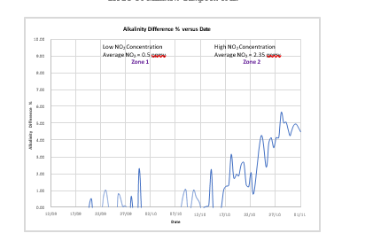
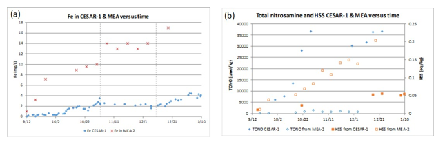
Also, an indicator of degradation is iron (Fe) concentration in an amine solvent. As can be seen from Fig 11a below the Fe concentration is significantly lower for CESAR1 as compared to MEA, indicating lower amine degradation caused by oxidative and thermal effects.
An additional comparison of solvent degradation for CESAR1 and MEA is shown in Fig 11b. Two trends are shown, total nitrosamine (TONO) and heat stable salts (HSS) versus time. The results demonstrate that degradation to heat stable salts is significantly higher for MEA as compared to CESAR1, whereas the opposite behaviour is observed for total nitrosamines. For CESAR1, the piperazine component is a secondary amine and is very prone to nitrosamine formation in the presence of NO2. MEA on the other hand is a primary amine and forms nitrosamine at a significantly lesser rate.
5. CESAR1 thermal reclaiming
The 2020 CESAR1 TCM Owners campaigns were performed with the already used CESAR1 solvent from the ALIGN CCUS test campaign in 2019 [14]. After roughly 1600 hours of CO2 capture plant operation, reclaiming of the solvent was deemed necessary at the start of the first owners test campaign in April 2020. The main goal was to remove the solvent degradation products and metals that had accumulated during operation and refresh the solvent for the first owners test campaign. Later, after an additional 2200 hours of CO2 capture plant operation was conducted which was followed by another thermal reclamation campaign in October 2020.
Both reclaiming operation periods were conducted in a semi-continuous operation mode similarly as previously done with MEA [15]. Fig. 12 shows a process flow diagram of the TCM plant, including the reclaiming system. The reclaimer was initially filled with a mix of demineralized water and an aqueous solution of 33 wt% NaOH. The mix was heated to around 130°C in the circulation loop before the lean amine feed was started and continued at a rate of approximately 2 m3/h. Approximately 8 ml/min of NaOH was added continuously during the reclaiming. Metals, heat stable salts (HSS) and degradation products accumulated in the reclaimer while amine and water were evaporated and led back to the stripper. This operation continued for 4 days before the amine feed was stopped. A total of 4.5 times the main plant total inventory was circulated through the reclaimer during the operation period. The temperature in the reclaimer was then raised to 144 °C in between addition of water for 2 days while the remaining amine and water evaporated and the amount of waste in the reclaimer was reduced. It was suspected that the high temperature could induce further degradation in the stream going back to the stripper, although only a limited amount of solvent is exposed to this temperature. The maximum temperature for the second reclaiming was thus limited to 137 °C. The reclaimer vessel was then emptied and cleaned, and the waste sent for disposal in three intermediate bulk containers (IBCs).
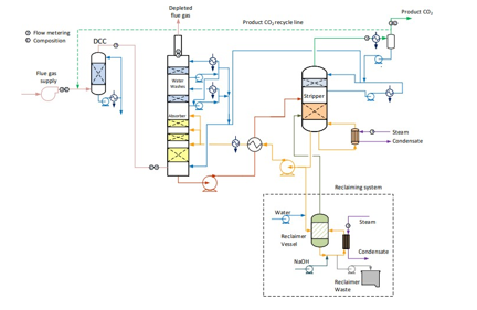
Table 8 below shows the removal rates from the reclaiming operations. The solvent quality is significantly improved during this operation. The average rates of removal were highly encouraging; 94% for metals, 89% for HSS and 83% for other known degradation products and the loss of amine through waste was lower than 5%. Long boil-off time at the end of reclaiming has been beneficial in terms of low amine loss. However, caution must be taken since exposure of high temperatures during boil-off can risk further degradation. The viscosity of waste was relatively low due to the low amine concentration, which makes draining of the reclaimer waste less challenging. Precautions are needed when handling thermal reclaimer waste as the content will contain nitrosamines and other potentially harmful degradation products.
Table 8. Loss of amine and removal of degradation products, heat stable salts and metals during reclaiming of CESAR1 solvent.
| Amine loss (%) | HSS removal (%) | Metals removal (%) | Degradation products removal (%) | |
| Reclaiming April 2020 | <5 | 89 | 95 | 84 |
| Reclaiming October 2020 | <5 | 89 | 93 | 82 |
6. Way forward to gain a better knowledge on degradation
TCM has gained valuable knowledge and experience with the use of the non-proprietary solvents 30 wt% monoethanolamine (MEA) and CESAR1 for CO2 capture. TCM has a laboratory scale solvent degradation rig (SDR) to allow further investigation on solvent degradation. This SDR can mimic the process conditions and configurations designed for CO2 capture at the TCM plant. For example, similar process conditions can be in place for the flue gas, absorber and stripper as carried out during CESAR1 test campaigns [16, 17]. TCM plans to use the SDR to gain further valuable insights into the rate of solvent degradation, identification of unknown degradation products and degradation reaction mechanisms/pathways. A SDR test campaign is planned with aged CESAR1 solvent, and the results will be compared with the CESAR1 test campaigns to close the current knowledge gaps. The SDR campaign results can provide a good understanding to solvent health and environmental risks for the CESAR1 solvent systems for CO2 capture. The results can also give sufficient knowledge of the solvent degradation expected and unexpected in a real CO2 capture plant.
The basic goal of the SDR campaign will be to demonstrate the bench-scale studies of solvent process degradation to identify unknown components, which were previously difficult to analyze. Online instruments such as FTIR and Raman spectrometer will be utilized with SDR for monitoring solvent hygiene. In addition, degraded components will be qualitatively and quantitatively characterized by using an advanced liquid chromatography-mass spectroscopy (LCMS) instrument. During this study, new analysis methods will be developed for the degraded components of the LCMS instrument, this work will be carried out at TCM lab.
7. Conclusions
In this article the solvent degradation for CESAR1 has been explored. Firstly, the expected degradation mechanism’s for the main amine components (piperazine and AMP) have been presented, along with the key degradation products which have been measured and quantified during TCM testing. Results of degradation have been compiled for tests for two flues gases (1) CHP flue gas (~ 3.7 vol% CO2 and ~ 14% O2) and (2) RFCC flue gas (~ 13.5 vol% CO2 and ~ 3.2% O2). For CHP flue gas, the results indicate a strong dependency on degradation rate as the NO2 concentration entering the CO2 absorber is elevated. This increase in NO2 concentration leads to a greater amount of nitrosopiperazine and other degradation products in the solvent. As the CESAR1 solvent becomes more degraded, approximately 5% of unknown degradation products have been idenitfied. For RFCC flue gas, higher amine loss rates through degradation have been observed and it is believed this can be attributed to the increase of impurities in the RFCC flue gas as compared to the CHP flue gas. Future work at TCM is planned to identify the unknown degradation products and to determine what additional process conditions are key contributors to solvent degradation. A comparison of overall degradation rates for CESAR1 versus MEA was also presented, comparing rates of degradation under similar flue gas conditions. The results indicate significant reduction in degradation rate for CESAR1 compared to previous MEA tests performed at TCM. Lastly, thermal reclaiming experiments have been performed on the degraded CESAR1 solvent with a goal of refreshing the solvent for future tests. Two semi-continuous thermal reclaiming operations were conducted, the average rates of removal were highly encouraging; 94% for metals, 89% for HSS and 83% for other known degradation products and the loss of amine through waste was lower than 5%.
Acknowledgments
The authors gratefully acknowledge the staff of TCM DA, Gassnova, Equinor, Shell and TotalEnergies for their contribution and work at the TCM DA facility. The authors also gratefully acknowledge Gassnova, Equinor, Shell, and TotalEnergies as the owners of TCM DA for their financial support and contributions.
References
- Freeman, S.A., (PhD thesis), Thermal Degradation and Oxidation of Aqueous Piperazine. University of Texas at Austin 2011.
- S.A. Mazari et al., Degradation study of piperazine, its blends and structural analogs for CO2 capture: A review. Int. J. Greenh. Gas Control 2014, 31, 214–228.
- Nielsen, P.T., et al., Piperazine degradation in pilot plants. EnergyProc. 2013, 37, 1912–1923
- Freeman, S.A., et al. Thermal degradation of aqueous piperazine for CO2 capture. 1. Effect of process conditions and comparison of thermal stability of CO2 capture amines. Ind. Eng. Chem. Res. 2012, 51 (22), 7719–7725.
- Freeman, S. A., et al. Thermal degradation of aqueous piperazine for CO2 capture: 2. Product types and generation rates. Ind. Eng. Chem. Res. 2012,51 (22), 7726–7735.
- Namjoshi, O., et al., Thermal degradation of piperazine blends with diamines. Energy Proc. 2013, 37, 1904–1911.
- Mark J. G, et al., Kinetics of N-Nitrosopiperazine Formation from Nitrite and Piperazine in CO2 Capture. Environ. Sci. Technol.,2013, 47 (7), 3528-3534.
- Wang, T., et al., Oxidative degradation of aqueous 2-amino-2-methyl-1-propanol solvent for post combustion CO2 capture. Ind. Eng. Chem. Res. 2012, 51 (18), 6529–6536.
- Wang, T., et al., Oxidative degradation of aqueous PZ solution and AMP/PZ blends for post combustion carbon dioxide capture. Int. J. Greenh. Gas Control 2014, 24, 98–105.
- Fine, N.A., et al., Thermal decomposition of N-nitrosopiperazine. Energy Proc. 2013, 37, 1678–1686.
- Gouedard, C., et al., Amine degradation in CO2 capture. I. A review. Int. J. Greenh. Gas Control 2012 10, 244.
- Naser, S. M., et al., Thermal Degradation Rate of 2-Amino-2-methyl-1-propanol to Cyclic 4,4-Dimethyl-1,3-oxazolidin-2-one; Mechanistic Aspects and Kinetics Investigation. Ind. Eng. Chem. Res., 2017, 56, 34, 9437–9445.
- Morken., et al., CO2 capture with monoethanolamine: solvent management and environmental impacts during long term operation at the Technology Centre Mongstad. International Journal of Greenhouse Gas Control, 2019, 82, 175–183.
- Benquet, et al., First Process Results and Operational Experience with CESAR1 Solvent at TCM with High Capture Rates (ALIGN-CCUS Project). 15th International Conference on Greenhouse Gas Control Technologies, GHGT, 2021.
- Morken, et al., Degradation and Emission Results of Amine Plant Operations from MEA Testing at the CO2 Technology Centre Monstad. Energy Procedia. 2017, 114, 1245-1262.
- Aslak, E. et.al., A new test rig for studies of degradation of CO2 absorption solvents at process conditions; comparison of test rig results and pilot plant data for degradation of MEA. 2013, 37, 717-726.
- Gjernes, E. et.at., Health and environmental impact of amine based post combustion CO2 capture, Energy Procedia. 2013, 37, 2013, 735-742.