
12. CO2 capture from RFCC flue gas with 30 wt% MEA at Technology Centre Mongstad, process optimization and performance comparison (2018)
Muhammad Ismail Shaha*, Gerard Lombardob, Berit Foståsc, Christophe Benquetd, Anne Kolstad Morkena, Thomas de Cazenovea
aTechnology Centre Mongstad, 5954 Mongstad, Norway bGassnova SF, Dokkvegen 10, 3920 Porsgrunn, Norway cEquinor ASA, PO Box 8500, 4035 Stavanger, Norway dTotal E&P Norge, Finnestadveien 44, Dusavik, 4029 Stavanger, Norway
Abstract
Aerosol based amine emission from post combustion carbon capture process is very challenging in terms of accurate online measurement, compliance to emission permit and operating cost due to high solvent makeup. At Technology Centre Mongstad (TCM), an advanced process configuration is developed and tested to control and reduce amine emissions in parallel to accurately measure MEA emissions by online FTIR. The advanced configuration consists of a Brownian diffusion filter upstream the absorber, RFCC water wash, special design and operation of online sampling system and a fractional cold rich amine bypass to the stripper. With the flue gas from the Residue fluidized catalytic cracker (RFCC), promising results are achieved by applying the advanced process configuration. MEA emissions are reduced to about 2 ppm and specific reboiler duty of 3.5 GJ/ton CO2 is demonstrated with a capture rate of about 90%.
1. Introduction
The Technology Centre Mongstad (TCM) is the world’s leading facility for verifying and improving CO2 capture technologies. TCM is located at Mongstad, one of Norway´s most complex industrial facilities. TCM has been operating since autumn 2012, providing an arena for qualification of CO2 capture technologies on an industrial scale. In autumn 2017, Gassnova (on behalf of the Norwegian state), Equinor (formerly Statoil), Shell and Total entered into a new ownership agreement securing operations at TCM until 2020. The owners of TCM started their most recent monoethanolamine (MEA) test campaign in June 2017 where a large number of public, industrial, research and academic stakeholders were involved [1]. The campaign included demonstration of a model-based control system, dynamic operation of the amine plant, investigating amine aerosol emissions and specific tests targeted at reducing the specific cost of CO2 capture. Through the testing, both flue gas sources currently available at TCM were used. These sources are the combined cycle gas turbine (CCGT) based heat and power plant (CHP) and the residue fluidized catalytic cracker (RFCC). They provide flue gases with a wide range of properties and CO2 content from 3.6 to 14 vol%. TCM is located next to the Equinor refinery in Mongstad. The Mongstad refinery is the source of both flue gases supplied to TCM.
Until 2017, TCM had not been able to operate the amine plant with RFCC flue gas due to very high amine emissions (> 20 ppmv) caused by sulfuric acid aerosol and dust particles present in the flue gas [2]. By installation of a Brownian diffusion (BD) filter upstream the absorber, more than 95% of the aerosol were removed and together with optimization of plant process parameters and configuration, the amine emissions were reduced to levels well below TCM’s emission permit (< 6 ppmv for amines.) this allowed for long term testing with RFCC flue gas in the amine plant.
TCM participated in the Climit Demo project AeroSolve (616125) that was led by SINTEF with NTNU, Uniper, Engie, TNO and the Road project as partners. The project aimed to close knowledge gaps related to aerosol emissions from CO2 capture plants whereas a part of the project TCM conducted a 3 months test campaign treating the RFCC flue gas with MEA under “work package 4” of the project (Testing at industrial demo scale). Based on the learnings gained through this campaign, TCM optimized and modified process configurations and online emission sampling system followed by further testing with the RFCC flue gas and MEA under MEA-4 campaign during Q2- 2018. The conventional amine process configuration was modified to an advanced amine process configuration which is able to efficiently capture CO2 from flue gases containing aerosol, and the sampling system was modified to accurately and reliably measure amine aerosol. Description of the sampling system, optimal TCM amine plant process configuration to minimize aerosol emissions and specific reboiler duty as main results from testing, is presented in the current paper.
2. TCM’s experience with Aerosol based emissions and its control
TCM is regulated under emission permit from the Norwegian environmental authority (Miljødirektoratet). The emission permit regulates amine plant’s emissions to air of ammonia (NH3), Amines (primary, secondary and tertiary) and aldehydes. Table 1 given below shows the allowable emission limits applicable to the amine plant.
| Emission component | Emission source | Emission limits | |
| Daily average concentration limit | Yearly limit(kg/year) | ||
| Ammonia (NH3) | Amine plant | 100 ppmv | 6,000 |
| Total Amines | Amine plant | 6 ppmv* | 2,800 |
| Total Aldehydes | Amine plant | 1 g/s |
Table 1. TCM Amine plant applicable emission permit.*
Maximum hourly averaged emission 15 ppmv.
Under normal operation conditions the amine plant capturing CO2 with 30 wt% MEA from CCGT flue gas has amine emissions to air below 1 ppmv and ammonia emissions about 10-20 ppmv [3] . TCM tested capturing CO2 with 30 wt% MEA for the first time, from the RFCC flue gas in spring 2013. It was soon found that emissions were very high and shortly further testing with RFCC and MEA were abandoned to avoid violation of the emission permit and to find ways to mitigate high amine emission to air.
To understand and control high amine emissions further tests with CCGT flue gas with recycled CO2 and controlled addition of RFCC flue gas supported by several manual isokinetic sampling of the depleted flue gas were conducted in autumn 2015 [11]. After through testing, control and repeatability of high amine emission tests, it was concluded that high amine emission is caused by sulfuric acid aerosol in the RFCC flue gas together with process conditions which causes high amine emission in the form of aerosol. From tests in autumn 2015, the need for RFCC flue gas aerosol removal, upgrade of the absorber water wash system and online flue gas sampling systems was deemed necessary to be able to run with RFCC flue gas and 30 wt% MEA in compliance to the applicable emission permit.
During late 2016 a high efficiency Brownian diffusion (BD) filter with flue gas capacity of 35,000 Sm3/h was installed downstream the Direct Contact Cooler (DCC) and upstream the absorber, followed by upgrade of the water wash systems to increase its cooling capacity to 12 MW (thermal), where 6 MW (thermal) on the lower water wash and 6 MW on the upper water wash system. The later upgrade allows keeping the plant in water balance and allows for flexible operation in terms of lean amine temperature, and selection of the ratio of cooling needed in the water washes.
During period summer-autumn 2017, the amine plant with the new installations was tested with 30 wt% MEA under the AeroSolve project. TCM amine plant’s ability to run with RFCC flue gas, 30 wt% MEA and compliance with the emission permit was demonstrated thoroughly and continuously supported by manual isokinetic sampling. During this period it was observed that the online flue gas analysis system was suffering stability issues due to accumulation of aerosol and degradation of amines. The online flue gas sampling system was upgraded and modified by TCM, to overcome aerosol accumulation and degradation of amines in the sampling line.
The upgraded online flue gas sampling system with advanced process configuration to reduce specific reboiler duty (SRD) was thoroughly and successfully tested during spring 2018 with 30 wt% MEA and RFCC flue gas.
2.1 TCM’s Amine plant
The amine plant is a generic and highly flexible CO2 capture plant designed and constructed by Aker Solutions and Kværner. The amine plant can either capture CO2 from CCGT flue gas or RFCC flue gas with a design CO2 production capacity of 80 tonnes/day and 200 tonnes/day respectively [4]. Figure 1 given below shows a simplified process flow diagram with online meters and instrumentation.
Flue gas from the blower is conditioned and saturated with water to the required temperature (normally 20-50°C) in the DCC. The CHP DCC system cools the flue gas from about 195°C down to the required temperature while the RFCC DCC saturates the flue gas from 20°C up to 50°C by injecting live steam into the DCC as the RFCC flue gas leaving the upstream (refinery side) flue gas desulfurization unit (FGD) is at around 20°C. Conditioned and water saturated RFCC flue gas enters the high efficiency BD filter where most part of aerosol and catalyst particles from the flue gas are removed. Filtered RFCC flue gas enters the rectangular absorber, where flue gas flows counter currently to lean amine solvent. The lean amine solvent can be fed either at 12m, 18m or 24m to the absorber structured packed bed. In the conventional configuration CO2 depleted flue gas enters the lower water wash followed by upper water wash to reduce VOC, NH3 and some amine emission to the air and condition the flue gas to the required humidity and thus keeps the plant in good water balance.
Rich amine from the absorber is pumped through the rich/lean cross plate heat exchanger to the top of either RFCC or CHP stripper depending on the flue gas source and CO2 amount to be produced. The RFCC stripper is a structured packed bed column equipped with water wash and shell and tube type natural thermosiphon reboiler which utilizes low pressure steam to regenerate rich solvent, CHP stripper is described elsewhere [4]. Stripped CO2 is cooled to about 20°C in the overhead condenser utilizing sea water. Condensate from cooled CO2 product is separated in the reflux drum and pumped back into the stripper top, while CO2 product is vented to the ambient via CO2 stack. The RFCC stripper is also equipped with a Lean vapor compressor (LVC) system, which can be lined-up with the RFCC stripper if required. In the LVC system, hot lean amine which is at bobble point is throttled to a lower pressure and fed to the flash drum generating steam. In the flash drum steam and lean amine solvent are separated. Steam from the flash drum is compressed to stripper bottom pressure in a compressor by the expense of electrical energy. The superheated steam from compressor is fed to the stripper which provides extra energy to regenerate rich amine and reduces consumption of low pressure steam. Lean amine solvent from the flash drum is pumped back to the absorber through rich/lean cross plate heat exchanger followed by lean amine cooler. The lean amine is cooled to the required feed temperature in the lean amine cooler.
The amine plant is heavily instrumented with dedicated online analyzers and flow meters. Details of the online analyzer and meters are given in Figure 1.
2.2 RFCC flue gas composition and its challenges for CO2 capture amine based process
RFCC flue gas contains high concentration of CO2, with about 14.7 vol% of CO2 (wet basis), 3.2 vol% of O2, 77 vol% N2 and saturated with water. This makes the RFCC flue gas equivalent to flue gas from coal power plant. Further details of the RFCC flue gas are given in Table 2 below. The concentration of trace elements in the RFCC flue gas fluctuates during normal operation.
| RFCC flue gas composition: | Inlet BD Filter | Inlet of Absorber | |
| N2 | mol% | 77.0 | 77.0 |
| Ar | mol% | 0.9 | 0.9 |
| O2 | mol% | 3.2 | 3.2 |
| CO2 | mol% | 14.7 | 14.7 |
| H2O | mol% | 4.2 | 4.2 |
| SO2 | ppmv | 5 | 5 |
| NOx | ppmv | 100 | 100 |
| NO2 | ppmv | 2.5 | 2.5 |
| NH3 | ppmv | 0.2 | 0.2 |
| CO | ppmv | 10 | 10 |
| Total Particulates | mg/Sm3 | 15-40 | <0.5 |
| H2SO4 Aerosol | mg/Sm3 | 10-25 | <0.5 |
| Salts | mg/Sm3 | 5-15 | <0.5 |
| Non-water soluble (SiO2,CaCO3,metals) | mg/Sm3 | 0-2 | <0.1 |
| Particle number concentration | aerosol/cm3 | 21* million | 300,000 to 500,000** |
Table 2. Typical RFCC flue gas composition upstream and downstream the BD filter.
*Aerosol conc. upstream the BD filter may vary from 15 million to 25 million. ** conc. downstream the BD filter varies between 300,000-800, 000 aerosol/cm3.
RFCC flue gas contains catalyst fines in the range of a micron to submicron sizes which are different in composition and nature to fly ash contained in coal power plant flue gas. If coal power plant flue gas is filtered for example with a bag house filter to reduce mercury, it will result in very clean flue gas comparable to RFCC flue gas downstream the BD filter. H2SO4 aerosol shown on mass basis in table 2 is equivalent to about 21 million aerosol/cm3 most of them are of submicron size.
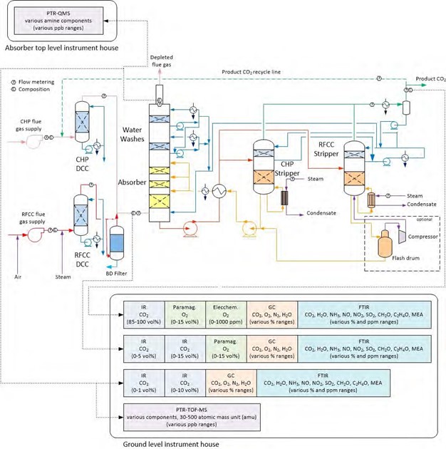
Figure 1. TCM Amine plant with two flue gas sources, CHP and RFCC with corresponding strippers, flue gas analyzers and meters.
BD filter reduces aerosol in the RFCC flue gas from around 21 million aerosol/cm3 to around 500,000 aerosol/cm3. Further details on performance of BD filter can be found elsewhere [2]. A bypass over the BD filter allows higher aerosol concentrations to the absorber in order to study its effects on emissions. The sensibility of advance amines may be compared to MEA at various aerosol concentrations and operational parameters.
Submicron aerosol larger than 0.1 µm grow in the absorber in the presence of supersaturated water vapor due to exothermic reaction of CO2 and MEA. The submicron aerosol absorb MEA from the flue gas in the region close to the lean amine inlet and absorber bulge zone, MEA has the highest partial pressure in this region of the absorber. Submicron aerosol from the absorption section will follow the depleted flue gas and will not be removed efficiently by conventional mesh pads or water wash packing bed(s). MEA emission in the form of aerosol can be reduced by reducing the number of aerosol nuclei in the feed flue gas to the absorber and by avoiding/reducing supersaturation in the absorber. At TCM the former is achieved by filtering the flue gas via the BD filter. The latter is achieved by operating the amine plant in such a way to minimize supersaturation in the absorber and water wash sections which allows for maximum MEA removal from the gas phase before the depleted flue gas enters the upper water wash.
Depleted RFCC flue gas containing MEA aerosol poses a great challenge to the online emission monitoring (FTIR, PTR-QMS, PTR-TOF-MS) system installed at TCM as MEA aerosol accumulate in the sampling system (filters, pumps, lines etc.) which makes online analysis erratic.
The existing sampling system for online emission monitoring in the TCM amine plant, which has been verified for gas phase emissions [5], is not suitable when aerosol are present in the sample flue gas. The problem was particularly experienced at higher MEA emissions (> 4-6 ppmv). With emissions around 2 ppmv MEA, the weight of the aerosol is in the range 30-50 mg/Sm3, while at 6 ppmv MEA, the weight of the aerosol may be up to 100 mg/Sm3 due to the increased diameter. The aerosol, which mainly consist of water, accumulate in the sampling system despite that sampling line has filters and is heat traced. The sampling system was designed for homogenous gas phase emissions and it has been proven to function very well when there are no aerosol present. In previous campaigns with CHP flue gas there has been good agreement between online measurements and manual isokinetic sampling and laboratory analysis [5].
In contrast aerosol carrying amines in the depleted RFCC flue gas accumulated in the sample line and associated filters, pump, and fittings resulting in erratic analysis and unreliable behavior. Upon occurrence of such problems, the sampling system was flushed several times but helped only for a short time. To ensure reliable measurements, proper design of online sampling system is required to avoid condensation, degradation and accumulation of aerosol and flue gas components. TCM’s online flue gas sampling was therefore modified to be able to efficiently evaporate aerosol, avoid accumulation, degradation and reliably and to accurately measure emissions.
2.3 Modified online flue gas sampling system
During tests with RFCC flue gas and 30 wt% MEA regular manual isokinetic sampling were collected and analyzed to make sure that the online emission monitoring system is working properly. The data was also used to properly design a robust online emission monitoring system. Several modifications to the online emission monitoring system were made during the period (2017-2018). This resulted in a robust and reliable emission monitoring system capable of accurately analyzing flue gas even in the presence of aerosol.
The modified online flue gas sampling system as shown in Figure 2, consists of an electric heat traced sampling probe equipped with 6 mm nozzle pointing at 90° to the horizontal plane and placed at 250 mm from the absorber stack’s inner wall. The sampling probe is flushed with cold instrument air if needed. The temperature of the heat tracing elements of the probe can be controlled from 40 to 200°C. Flue gas sample via the probe leads to evaporator, the evaporator is a 316ss double pipe type of electric heater, where the flue gas sample travels in the annulus. The flue gas sample in the annulus of the evaporator is heated by 622 W heating elements installed on the outside of shell and the heating elements inside the inner rod located in the center of the evaporator. The rod runs along the length of the evaporator. The annulus of the evaporator is 12.5 mm wide and 670 mm long. A suction pump sucks 1 m3/h of flue gas sample through the probe resulting in a flue gas sample velocity similar to the velocity in stack, which makes it isokinetic. The flue gas has a residence time of ~4 seconds in the evaporator. Flue gas sample from the pump is filtered with several filters ranging in sizes from 0.1 µm to 10 µm located in the filter house.
The filtered flue gas sample delivers a feed of 0.4 m3/h to the online FTIR over a flowmeter while rest of the sample is routed back to the absorber. The FTIR analyzer is located in the analysis house close to the bottom of the absorber. A sampling line of 110 m length in sulfonated and polished stainless steel which is heat traced and insulated carries the flue gas sample to the FTIR analyzer. This arrangement avoids accumulation of aerosol and condensable components on the surfaces. To avoid chemical degradation of the sample the flue gas sample is not overheated and kept close to 80°C.
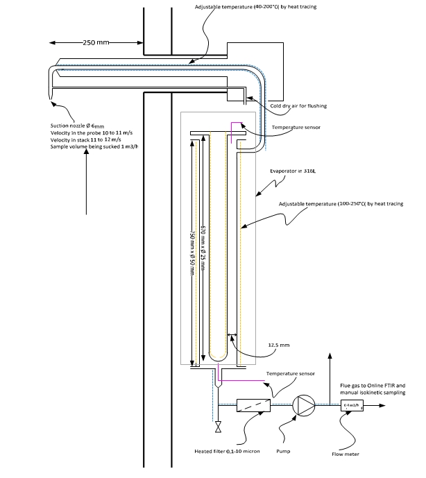
Figure 2. Sketch of TCM modified online flue gas sampling system able to accurately analyze flue gas containing aerosol.
2.4 Isokinetic sampling sketch and description
To verify online sampling system, manual isokinetic sampling of the absorber depleted flue gas for quantification of the concentration of emitted chemical components, were planned to be taken several times on weekly basis and more frequent in demanding periods during testing with RFCC flue gas.
In 2016, TCM further developed the existing method for isokinetic sampling to enable capturing very fine liquid droplets and aerosol. Up to then, the amine plant had mainly been used for capturing CO2 from the CCGT flue gas with very low to almost negligible concentration of SO2 and no aerosol. The development resulted in a modified manual sampling method for amine emission in presence of aerosol. Figure 3 illustrates a sketch of the modified manual isokinetic sampling method. The sampling train consists of a cold probe, a condenser, a dry impinger with jet inlet design, distribution manifold and 0.05 M H2SO4 impinger train. The method has been further optimized since 2016, and the mist trap now consists of only one bottle with jet inlet and no glass wool. The jet-formed inlet of the bottle accelerates the gas containing particles/aerosol/droplets and over a fixed distance lets the particles impinge against a flat glass surface at higher velocity. During this operation droplets gets broken and agglomerated to bigger droplets which are less prone to further re-entrainment.
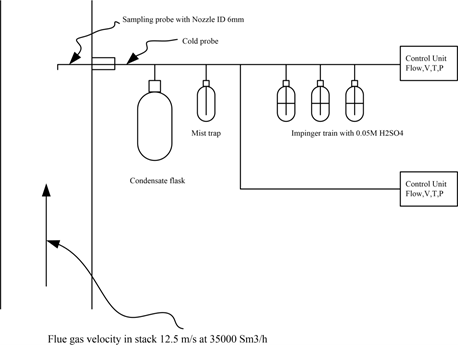
Figure 3. Modified manual sampling train configurations at TCM for collection of mist and flue gas sample. This method has been further optimized and the mist trap now consists of only one bottle with jet inlet and no glass wool.
2.5 Comparison of manual isokinetic and online emission results
While running with RFCC flue gas the TCM online emission monitoring system was suffering from severe aerosol accumulation resulting in erratic emission numbers. Erratic functioning of the online emission monitoring system was monitored by comparing water concentration in the depleted flue gas reported by FTIR to calculated water concentration from steam table based on the actual temperature and pressure of the depleted flue gas.
Fluctuations or discrepancies between the measured water concentration and calculated concentration reveal problems with online emissions monitoring system. Figure 4a shows such an example.
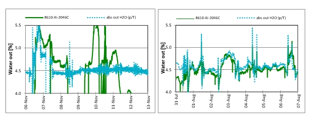
Figure 4a (left) Water measured by online FTIR (Green solid line) showing fluctuations and discrepancy problems with the sampling system. water concentration from FTIR does not match with calculated water concentration (dotted line in light blue) in the depleted flue gas. All process parameters were kept unchanged during this period. Figure 4b (right), shows good agreement between water concentration both from the FTIR and calculated.
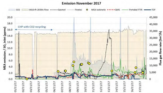
Figure 5 Comparison of isokinetic sampling results to the non-modified online sampling system.
Figure 5 shows comparison of FTIR (Gasmet) and isokinetic results from November 2017, before modification of the sampling system. FTIR mentioned in this paper is FTIR (Gasmet) and will be denoted by FTIR for reference. In Figure 5, on left side, FTIR results compared to manual isokinetic show good agreement during this period the plant was running with CHP flue gas with CO2 recycle having similar CO2 conc. as RFCC flue gas but free of aerosol and has less SO2. From 6th of November the flue gas source is switched to RFCC. During the first couple of days differences in results from FTIR and Isokinetic is not very pronounced. From the 8th of November the difference in results from isokinetic and FTIR begins to increase this can also be noticed from Figure 4a showing mismatch between the water conc. measured by FTIR and calculated. This instance reveals accumulation of aerosol in the sampling system and perhaps enhanced by non-representative sample due to the fact that the probe for FTIR was installed at location S6 as shown in Figure 11. S6 is located in the concrete absorber wall where the probe may not have received a representative sample due to its non-optimal design. This was verified by manual sampling at S6 which does not match manual isokinetic results at S14 (shown in Figure 11). From 11th of November the deviation in results from FTIR to isokinetic gets very large, the behavior renders the online system inadequate for flue gas containing aerosol. Therefore, it was deemed necessary to modify the existing online sampling system to be able to analyze accurately and reliably in the presence of aerosol in the flue gas.
The objective of the TCM modified online sampling system is to be able to measure total amine emission in the depleted flue gas both in the form of aerosol and gas phase, and to increase the online systems availability and reliability with challenging flue gases.
Figure 6 shows comparison of results from the modified online sampling system with FTIR installed at S14 and manual isokinetic samples. All process parameter (i.e.) flue gas flow rate, CO2 concentration in the inlet flue gas, lean amine temperature, water wash(s) process parameters, CO2 capture rate, and lean amine flow rate were kept unchanged while performing manual isokinetic sampling and collecting data from the online FTIR.
It is obvious from Figure 6 that isokinetic and online FTIR results from the modified sampling system are in good agreement and is not suffering from aerosol accumulation and degradation. The modified system is tested thoroughly for more than two months with RFCC without any problems of aerosol accumulation.
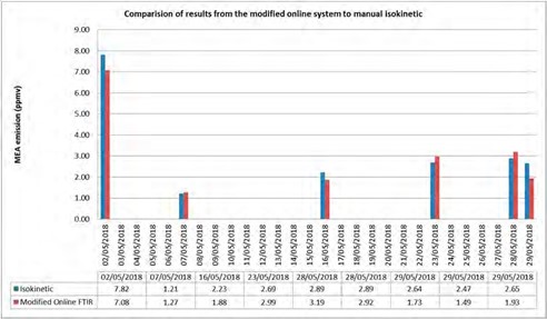
Figure 6. Comparison of results from the modified online sampling system with FTIR and isokinetic.
3. Process optimization for energy consumption and low emission
During the AeroSolve CLIMIT project (August-November 2017), testing with RFCC flue gas and 30 wt% MEA was conducted to find optimal process conditions resulting in low emissions and optimum SRD. Some of the tests conducted during AeroSolve project were revised and further optimized with the modified online sampling system in operation during spring 2018 under TCM owner’s MEA-4 test program. During all these tests caustic soda solution was injected in the RFCC DCC to reduce SO2 in the flue gas entering the absorber.
Some of the process parameters and plant configuration which were optimized in the AeroSolve project are:
- Lean amine temperature
- Lean amine loading for minimum Specific reboiler duty (SRD)
- Process plant configuration to result in minimum emissions
As a result, an advanced process plant configuration together with the mentioned modified online sampling system was developed which results in lower SRD and low emissions. Details of the optimized process parameters are given below.
3.1 Lean amine temperature optimization
CO2 absorption in chemical solvents like MEA, MDEA or MEA+AMP etc. is an exothermic process resulting in temperature increase of the absorbing solvent and flue gas in mutual contact. The temperature increase is largest in the absorber bulge zone as shown by the temperature profile of the TCM amine absorber in Figure 7. Due to heat generation and temperature increase in the absorber bulge zone water is evaporated from the bulk of the solvent to the gas phase and thus saturates the flue gas at a given temperature, pressure and composition. The saturation of gas phase with water can be further increased to supersaturation, S as given by equation (1), by creation of aerosol (including both homogenous and heterogeneous aerosol) due to rapid quenching with cold lean amine and in presence of large amount of submicron foreign nuclei. Aerosol formation and its growth in gas-liquid contactors such as absorbers and scrubbers has been extensively studied for quenching of acid gases [6], [7], [8].
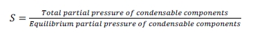
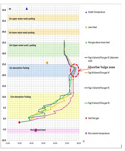
Figure 7. Absorber temperature profile, running with RFCC flue gas. CO2 capture of 85%.
For homogenous supersaturation a higher degree of saturation is required S>2 [9], depending on temperature and composition. For heterogeneous aerosol formation, the degree of supersaturation required could be as low as close to S~1 due to presence of large number of nuclei available in the gas phase. The aerosol formed in the absorber bulge zone will follow the flue gas stream to the downstream water wash system(s). The aerosol may grow further due to condensation, coalescence and process parameters which favor rapid quenching.
Lean amine entering the absorber is typically around 35-40°C where the highest bulge temperature in the absorber is around 50-55°C for CCGT type of flue gas at 85% CO2 capture [5], while for RFCC or coal flue gas having around 14% CO2 the bulge temperature is around 75-78°C for 85% CO2 capture with 30 wt% MEA. The environment for creation and growth of aerosol due to supersaturation will be favorable if the temperature difference between the lean amine and absorber bulge (ΔTbl) is large.

Therefore, keeping small difference between the lean amine temperature and bulge temperature will help reducing aerosol formation and hence reduce amine aerosol emissions. On the other hand running CO2 capture plants with high lean amine temperature to reduce the ΔTbl may lead to increased SRD due to the fact that less energy from hot lean amine is recovered in the rich lean cross heat exchanger. As a result more energy is lost to cooling water in the water wash system. To reduce the energy loss in a conventional amine plant configuration, ΔTbl needs to be kept largest possible to allow for optimal SRD and acceptable amine emission in compliance to the applicable emission permit.
Several tests were conducted during the testing at TCM within the AeroSolve project to optimize the lean amine temperature in terms of reducing emissions. Figure 8 shows MEA emission as function of ΔTbl.
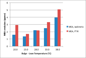
Figure 8 shows reduction in MEA emissions by reducing ΔTbl.
From Figure 8 it is obvious that MEA emissions are reduced by reducing ΔTbl. This supports the theory of reducing supersaturation in the gas phase reduces MEA emissions. During tests with RFCC flue gas TCM targeted to run the plant with less than 1-2 ppm of MEA emissions. Based on the results it was decided to keep ΔTbl below 25°C for tests with RFCC flue gas at 87% CO2 capture rate which allows keeping MEA emissions below 2 ppm.
3.2 Lean amine loading for minimum Specific reboiler duty (SRD)
The plant performance was optimized for 18 m absorber packed height, with about 14% CO2 by varying lean solvent flow rate and manipulating steam flow rate to stripper reboiler to find process conditions resulting in 87% CO2 capture with lowest SRD. As the online sampling system during the AeroSolve project was not able to accurately and reliably measure MEA emissions resulting from tests with RFCC flue gas, it was decided to run SRD optimization tests with CHP and CO2 recycle flue gas to avoid any breach of emission permit. CHP flue gas with CO2 recycle flowrate from the stripper overhead was adjusted, to achieve CO2 concentration in the flue gas at absorber inlet similar to RFCC flue gas CO2 concentration.
Table 3 given below summarizes range of process parameters tested during SRD optimization tests. At each solvent flow rate, the steam pressure was manipulated and hence the steam flow rate to achieve 87% CO2 capture. At stable conditions, lean and rich solvent samples were collected for analysis of MEA and CO2 concentration. After every 24 hours, the solvent flow rate was changed to the next set point and the procedure was repeated at each solvent flow rate.
| Parameter | UoM | Range |
| Number of test cases | 10 | |
| Absorber Packing height | m | 18 |
| Flue gas flow into absorber | Sm3/h (w) | 35,000 |
| Flue gas composition: | ||
| CO2 | mole% | 13.1-13.5 |
| H2O | mole% | 4.0 – 4.2 |
| O2 | mole% | 12.2 – 13.5 |
| Flue gas inlet temperature | °C | 29 – 30 |
| Conc. of MEA in lean solvent (CO2 loaded) | wt% | 28-30.2 |
| Lean solvent flow rate | kg/h | 100,000 – 165,000 |
| Lean solvent temperature | ºC | 50 to 55 |
| Liquid to Gas ratio | kg/Sm3 | 2.8-4.6 |
| Stripper bottom temperature | °C | 119.5 – 122.6 |
| CO2 capture rate | % | 86-89 |
| Stripper pressure | barg | 0.95-0.96 |
Table 3. List of process parameters during SRD optimization tests.
Figure 9 shows results for the SRD optimization tests. Capture rate during these tests was within 86-88% as denoted by red david (*) stars in the figure. For the targeted 86-89% CO2 capture, a minimum SRD of 3.67 GJ/ton CO2 was achieved. For optimal SRD, a lean solvent circulation rate of 120,000 kg/h with 30 wt% MEA is required while utilizing 18 m packing height of the absorber bed. Table 4 summarizes some more details for tests reported in Figure 9. More details about SRD(Meth 1) and SRD( Meth 3) as shown in figure 9. can be found elsewhere [10].
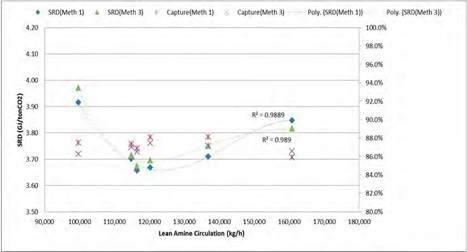
Figure 9. U-curve for SRD optimization, CHP flue gas with CO2 recycle and 30 wt% MEA.
| Case ID | Flue gas flow | Lean amine flow | Lean amine loading(mol | CO2 Capture | SRD (GJ/ton |
| rate (Sm3/h) | rate (kg/h) | CO2/mol MEA) | rate (%)* | CO2)* | |
| 2C-CHP- 6C Recy | 33,908 | 99,670 | 0.160 | 88.3% | 3.92 |
| 2C-CHP- 6A Recy | 33,900 | 114,873 | 0.19 | 87.3% | 3.70 |
| 2C-CHP- 5C Recy | 33,934 | 116,455 | 0.204 | 87.3% | 3.67 |
| 2C-CHP- 8A Recy | 33,918 | 120,360 | 0.199 | 87.4% | 3.67 |
| 2C-CHP-3 Recy | 33,699 | 136,867 | 0.251 | 88.1% | 3.71 |
| 2C-CHP-4 Recy | 33,874 | 160,821 | 0.273 | 85.9% | 3.85 |
*Tabulated Capture rate and SRD is based on Meth 1.
Table 4. List of process parameters during SRD optimization tests.
4. Advanced process configuration for reduction and control of amine aerosol emission
TCM developed and tested an advanced novel concept to reduce and control amine aerosol emission and improve the energy efficiency of the overall CO2 capture process. The advanced process configuration was tested for an extended period during spring 2018 under TCM owner’s MEA-4 campaign. The advanced process configuration’s performance was independently verified by a third party, Electric Power Research Institute (EPRI) in May 2018. The independent verified advanced process configuration’s performance with RFCC flue gas will serve as baseline for bench marking other amine based technologies. The independent verified RFCC baseline will be published later. Following modifications were made to the amine plant prior to running tests with RFCC flue gas under the MEA-4 campaign, in order to allow for accurate and reliable online emission monitoring, amine aerosol emission reduction, and improve the energy efficiency of the overall process.
- Modification of online emission monitoring system
- Modification of the 3rd absorption bed to “RFCC water wash”
- Installation of cold rich by pass line to the stripper
- Installation of Brownian diffusion (BD) filter
Brownian diffusion filter was installed in December 2016 and thoroughly tested with RFCC flue gas during 2017 and 2018. Details about performance of TCM BD filter can be found elsewhere [2]. Modification of online emissions monitoring system with FTIR is described in section 2.3 while rests of the modifications are described below.
4.1 Modification of the 3rd absorption bed to RFCC water wash
The RFCC flue gas downstream the BD filter contains around 500,000-800,000 aerosol/cm3, most part of the aerosol are submicron (0.1-0.5 µm) [11]. In absorber the submicron aerosol grow by condensation of water and coalescence followed by absorption of MEA present in vapor phase in the bulge zone. Majority of aerosol carrying amine from the absorber bulge zone will follow the supersaturated depleted flue gas to downstream sections of the absorber (i.e) water wash(s) and demisters.
A conventionally designed amine plant treating flue gas which contains aerosol and particulates cannot remove submicron aerosol. This is due to the fact that in a conventional absorber system, the depleted flue gas from absorption section is quenched abruptly to keep the plant in water balance and recover some amines and ammonia. Abrupt quenching in the presence of nuclei generates and grows more aerosol due to heterogeneous supersaturation which results in increased emissions. Therefore, abrupt quenching of the depleted flue gas needs to be avoided when amine are present in the gas phase. At TCM a three stage water wash system is tested in order to mitigate the aerosol emissions. The system is tested with up to 2000,000 aerosol/cm3 in the flue gas at the absorber inlet.
Abrupt quenching of the depleted flue gas containing aerosol at TCM is avoided by a special designed water wash which is termed “RFCC water wash” utilizing the pre-existing 6 m deep upper absorption bed. As suggested by its name the RFCC water wash is operated when capturing CO2 from RFCC flue gas. The purpose of the RFCC water wash is to remove as much as possible of the amines in gas phase with hot and relatively clean water from the upper water wash [12]. Simultaneously, large aerosol above 5 µm generated above the bulge area are captured in the RFCC water wash. In the future, a demister shall be installed upstream of the RFCC water wash in order to capture larger aerosol and increase the RFCC water wash efficiency.
The lower water wash is operated at the highest possible temperature in order to capture the remaining amines in gas phase and to avoid water condensation on aerosol.
- The upper water wash cools down the flue gas for the plant water balance.
- The RFCC water wash consists of 6 m Flexipac 2X (SS) structured packing with equivalent diameter similar to the absorber equivalent diameter and a special distributor.
The special distributor has a capacity corresponding to the total clean water condensed in the upper water wash. This is about 6-8 m3/h of water during normal conditions. Hot water at around (60-70°C) either from the upper or lower water wash, preferably from the upper water wash together with inherent leakage of about 1 m3/h of water from the lower water wash collector tray is fed to the RFCC water wash. Water fed to the RFCC water wash distributor irrigates the packing and aerosol in the depleted flue gas counter currently contacts hot water. Aerosol in the depleted flue gas grow to a larger size which makes it possible to be removed from the flue gas in the RFCC water wash. Major part of aerosol containing amine is recovered here. Water from the RFCC water wash containing removed aerosol flow down to the absorber packing and eventually to absorber sump. Figure 10. shows details of the RFCC water wash configuration.
The amine captured in each water wash is estimated based on the laboratory analysis of the water wash circulation water and the flow meters of each water wash drain. The tests confirm that more than 90% of the amines are captured in the RFCC water wash. 5% to 8% are captured in the lower water wash. Less than 2% are captured in the upper water wash. The total amines captured in the three water washes correspond to a concentration up to 2,000 ppmv of MEA in the flue gas upstream the water washes. As the theoretical MEA concentration in the gas phase is lower than 400 ppmv, it is deducted that most of the amines captured in the RFCC water wash are caused by MEA condensed on aerosol.
A different water wash configuration is tested elsewhere [12] with a limited water flow to the lower water wash further operation parameters are not available in the public domain.
At TCM depleted flue gas from RFCC water wash continues to lower water wash where the flue gas is cooled by removing about 1 MW of heat. From the lower water wash the depleted flue gas leads to upper water wash and cools down to a temperature just above the flue gas inlet temperature in order to keep the plant in water balance.
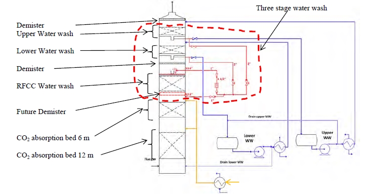
Figure 10. Water wash configuration for the TCM amine plant absorber.
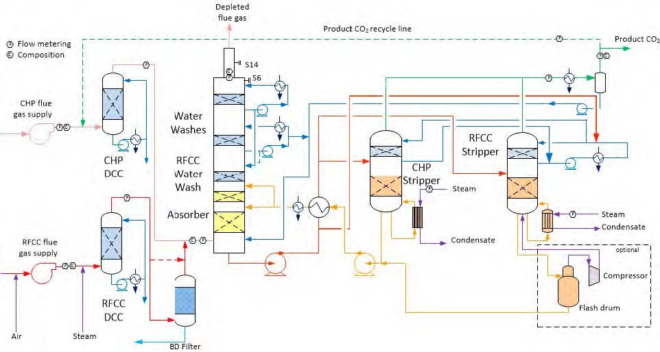
Figure 11. TCM Advanced process configuration for emissions control and optimal SRD. RFCC WW and rich amine bypass over cross heat exchanger is shown in the figure.
4.2 Installation of cold rich by pass line
As discussed in section 3.1, lean amine inlet temperature to absorber needs to be kept around 55°C while capturing CO2 from RFCC flue gas, this gives a ΔTbl~ 23°C. Lean amine temperature of 50°C or above can be achieved by two ways:
- Bypassing a fraction of hot lean amine over rich-lean cross heat exchanger
- Bypassing a fraction of cold rich amine over rich-lean cross heat exchanger
By applying the first approach a fraction of hot lean amine bypasses over the rich-lean cross exchanger, the bypass hot lean is mixed with cold lean amine exiting the cross heat exchanger and fed to the absorber without further cooling in the downstream trim cooler. Bypassing a fraction of hot lean amine increases SRD because the available recoverable heat in the cross heat exchanger reduces and the extra heat in the bypass stream is transferred to flue gas and thus lost in the cooling water.
By applying the second approach a fraction of cold rich solvent downstream the rich pump bypasses the cross rich-lean heat exchanger and fed to the stripper overhead system. Via the stripper overhead system, the rich bypass stream enters the stripper water wash section and functions as extra reflux by condensing water from the gas phase in the stripper top section accompanied by further cooling in the stripper top section. The energy from condensation of water in the stripper top section is recovered in the cold rich stream running down the stripping section thus reduces the energy lost in the overhead condenser. Around 2/3 of water in the stripper top section is condensed by the cold rich amine stream. While 1/3 of the water in the hot stripper gas stream is condensed in the overhead sea water cooled condenser. This reduces SRD from 3.67 to 3.5 GJ/ton CO2 at similar conditions. The second approach as described above was implemented to the TCM amine plant as illustrated in Figure 11 and tested thoroughly. The advanced configuration consisting of BD filter, three stage water wash system, cold rich bypass to stripper and modified online emission monitoring system was tested successfully over a long period and enabled TCM to run amine plant with RFCC in compliance with the applicable emission permit in an efficient manner. Table 5 summarizes results achieved with the advanced configuration and RFCC flue gas.
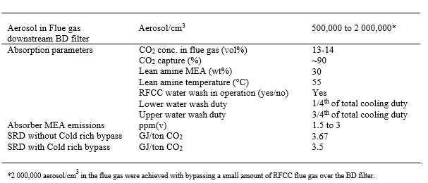
Table 5. Performance of advanced process configuration of amine plant.
Conclusion
TCM has developed and tested an advanced amine plant process configuration for RFCC flue gas with 30 wt% MEA. The advanced configuration in addition to conventional configuration consists of a Brownian diffusion filter, three stage water wash system, online sampling system tolerating aerosol, fractional bypass of cold rich amine stream and operational parameters which enables to reduce aerosol based amine emissions to around 2 ppm and SRD of 3.5 GJ/ton CO2. To avoid MEA emissions above 2 ppmv the flue gas entering the absorber should have no more than 1000,000 aerosol/cm3, the ΔTbl needs to be kept within 25°C and any abrupt quenching of aerosol containing depleted flue gas needs to be avoided. The latter is achieved by operating the RFCC water wash with the special procedure described in this paper. To reduce SRD a fraction of rich stream should be bypassed over the lean rich cross heat exchanger and fed to the stripper, this helps to reduce steam demand and thus lowers SRD. The sampling line for the online analysis and monitoring should be designed to avoid accumulation and degradation of chemical species and should be able to evaporate all chemical species and keep it in gaseous form.
Acknowledgements
The authors gratefully acknowledge the staff of TCM DA, Gassnova, Equinor, Shell and Total for their contribution and work at the TCM DA facility. The authors also gratefully acknowledge TCM owners and the Climit Demo project AeroSolve (616125) for their financial support and contributions.
References
- The Open-source Centre at TCM, https://catchingourfuture.com/
- Lombardo G, Shah MI, Fostås B, Hvidsten OA, Faramarzi L, Cazenove TD, Lepaumier H, Rogiers P. Results from aerosol measurement in amine plant treating gas turbine and residue fluidized catalytic cracker flue gases at the CO2 Technology Centre Mongstad (GHGT-14, 2018)
- Morken A.K, Pedersen S, Kleppe ER, Wisthaler A, Vernstad K, Ullestad Ø, Flø NE, Faramarzi L, Hamborg ES. Emission results of amine plant operations from MEA testing at the CO2 Technology Centre Mongstad, Energy Procedia 63(2014), 6023-6038
- Gjernes E,Pedersen S,Cents T, Watson G, Fotås BF, Shah MI, Lombardo G, Desvignes C, Flø NE, Morken AK, Cazenove TD, Faramarzi L,Hamborg ES. Results from 30 wt% MEA performance testing at the CO2 Technology Centre Mongstad, Energy Procedia 114(2017)1146-1157
- Faramarzi L,Timsen D,Hume S,Maxon A,Watson G,Gjernes E,Fostås BF,Lomarado G,Cents T,Morken AK,Shah MI,Cazenove TD,Hamborg ES. Results from MEA testing at the CO2 Technology Centre Mongstad: Verification of baseline results in 2015. Energy Procedia 114(2017)1128-1145
- Gretscher, H., Schaber, K., Aerosol formation by heterogeneous nucleation in wet scrubbing processes, Chem. Eng. Process. Process Intensif., 38, 541–548, 1999.
- Wix, A., Schaber, K., Ofenloch, O., Ehrig, R., Deuflhard, P. Simulation of Aerosol Formation in Gas-Liquid Contact Devices, Chem. Eng. Commun., 194, 565–577, 2007.
- Brachert, L., Kochenburger, T., Schaber, K., Facing the Sulfuric Acid Aerosol Problem in Flue Gas Cleaning: Pilot Plant Experiments and Simulation, Aerosol Sci. Technol.,47, 1083–1091, 2013.
- Purvil Khakharia. Aerosol-based Emission, Solvent Degradation, and Corrosion in Post Combustion CO2 capture (PhD thesis 2015)
- Hamborg ES, Smith V, Cents T, Brigman N, Pedersen OF, Cazenove TD, Chhaganlal M,Feste JK, Ullestad ØmUlvatn H,Gorset O,Askestad Inga,Gram LK, Fostås BF, Shah MI, Maxon A, Thimsen D. Results from MEA testing at the CO2 Technology Centre Mongstad. Part II: Verification of baseline results, Energy Procedia 630(2014) 5994-6011
- Lombardo G, Fostås BF, Shah MI, Morken AK, Hvidsten OA, Mertens J, Hamborg ES. Results from aerosol measurement in amine plant treating gas turbine and Residuel Fluidized Catalytic Cracker flue gases at the CO2 Technology Centre Mongstad. Energy Procedia 114(2017) 1210-1230
- Moser P, Schmidt S, Stahl K, Vorberg G,Lozano GA, Stoffregen T, Røsler F. Demonstrating Emission Reduction-Results from the Post combustion Capture Pilot Plant at Niederaussem. Energy Procedia 63(2014) 902-910.