
7. Critical Knowledge for CO2 - Intensive Industries to Implement Amine-Based Carbon Capture (2021)
Stefania Osk Gardarsdottir1, Leila Faramarzi2,3, Kristin Jordal1,Matthew Campbell2
1SINTEF Energy AS, PO Box 4761 Torgarden, 7465 Trondheim, Norway 2Technology Centre Mongstad, 5954 Mongstad, Norway 3Vallourec, 27, Avenue du Général Leclerc, 92100 Boulogne Billancourt
Abstract

This paper has been written to provide some decarbonization guidelines and recommendations for different CO2 intensive industrial applications, such as, Cement, Oil Refineries, Waste to Energy, Steel, H2 Production, Aluminum and Pulp & Paper. Relevant information has been provided for any potential project targeting a significant reduction in CO2 emissions. The importance of flue gas characterization has been indicated, including which typical components in the flue gas should be measured, which are important for properly planning and designing a CO2 capture project. Additionally, based on Technology Centre Mongstad (TCM) experience with both clean flue gas (CCGT) and more contaminated flue gas (RFCC), recommendations are given for the importance of good solvent hygiene and maintaining low amine emissions to the stack and surrounding environment. It is expected that each of the industrial applications described will lie somewhere between the CCGT and RFCC in terms of flue gas cleanliness. It has also been demonstrated that material integrity of a CO2 capture plant can be compromised if solvent hygiene is not maintained. Also, how the material integrity and selection can have considerable impact on CO2 capture plant cost and reliability of operation.
1. Introduction
The importance of CO2 abatement to curb global warming is becoming increasingly evident. In “A Clean Planet for All, the new European strategic vision for a prosperous, modern, competitive and climate-neutral economy”, it is stated that deployment of carbon capture and storage (CCS) is necessary for tackling CO2 emissions that cannot be cut through e.g. increasing energy efficiency and renewables [1].
CO2 capture and storage (CCS) is one way to cut CO2 emissions in carbon-intensive industries, which account for around a quarter of global direct CO2 emissions [2]. For some industry sub-sectors, as in the case of e.g. cement production, CCS is the only option to realize deep emission cuts [3]. CO2 capture with amines is the most mature technology and is already deployed at scale e.g., at Boundary Dam (Coal-fired power plant, Canada). Furthermore, capture with amines is currently progressing towards realization at industrial scale in several emerging European CCUS (carbon capture, utilization, and storage) projects e.g., AVR Waste to Energy, Heidelberg Materials Heidelberg Cement, and Fortum Oslo Varme Waste to Energy.
It is important that these and other initial industrial-scale capture projects are implemented in a successful manner, to create positive momentum and lay a foundation for additional successful projects, which is key for deploying full
Electronic copy available here.
CCUS value chains. The “learning and experience” effect from the early projects will help to optimize and de-risk operations of the forthcoming ones. And like other chemical industries, building up experience together with continued R&D will result in project cost improvements. Also, with accumulation of operational experience in capturing smaller volumes of CO2 (a strategy followed by several emission sources across Europe), it will become possible to increase captured CO2 volumes.
There are various technology suppliers in the market, offering amine technologies to CO2-intensive industries with limited commercial experience in the field of CO2 capture. The CO2-intensive industries must be enabled to make an informed choice of a technology that suits their specific application. Such industries must also be aware how the operation of an installed amine plant can affect the overall OPEX and environmental footprint of their entire production.
Against this background, the aim of the present paper is to summarize the experience from Technology Centre Mongstad (TCM) and SINTEF regarding 1) CO2 capture integration into CO2-intensive industries; 2) Importance of proper flue gas characterization; 3) Solvent hygiene, material integrity and cost; 4) Emissions from amine plants.
2. Requirements for Integration of CO2 capture in energy-intensive industry
Considering industry sub-sectors, steel, cement, and petrochemicals (e.g., oil refineries and H2 production) account for about 70% of direct industrial CO2 emissions. Examples of key characteristics relevant for amine-based CO2 capture for these industries as well as several other important industry sub-sectors are listed in Table 1.
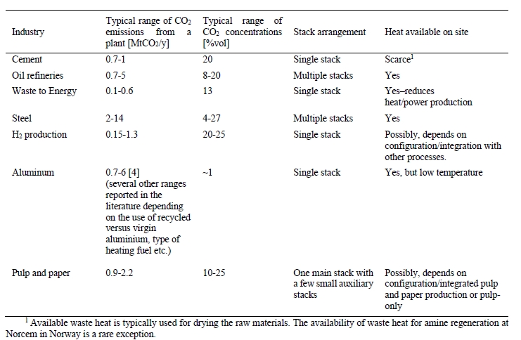
Table 1. Overview of characteristics of key energy-intensive industries relevant for CO2 capture.
Amine-based CO2 absorption primarily requires energy in the form of heat, for stripping CO2 from the solvent, and electricity, to drive pumps and fans. The cost of heat, most often in the form of steam, is generally the largest cost factor of the CO2 absorption process. Therefore, any excess heat of sufficient quality available on the industry plant site can potentially improve the economics of the CO2 absorption process considerably. For use of available excess heat, in addition to having sufficient quality, the properties of the heat-carrying fluid will be pivotal and will affect the cost and space required for heat exchangers.
Furthermore, for near-and medium-term deployment of CCS, retrofittable CO2 capture options are essential for brownfield industrial installations. In the CEMCAP project [4] several factors were defined to analyze retrofitting cement facilities with CO2 capture; Furthermore, for near-and medium-term deployment of CCS, retrofittable CO2 capture options are essential for brownfield industrial installations. The implication that several of these factors can have on the plant economics has recently been discussed in the work of Roussanaly, Berghout [5];
2.1 Impact on production of the key product
For any energy-intensive industry, producing a high-quality product is the number one priority. It is therefore of highest importance that the integration of the CO2 capture process does not impact the product quality and overall operability of the industrial plant. This could be a challenge for CO2 capture technologies requiring deep integration with the industry plant’s core processes. For end-of-pipe technologies, such as amine CO2 absorption, this is generally not considered a challenge for neither retrofit nor greenfield applications.
2.2 Equipment and footprint
Space requirement of CO2 capture equipment can be a significant challenge for industrial sites, especially brownfield industrial sites which have not been designed to accommodate CO2 capture equipment with a significant footprint. Thus, modifications to the existing plant or compromises in design, resulting in sub-optimal layout of the capture process, e.g., replacing existing process units, re-routing flue-gas streams or placing parts of the CO2 capture process in different locations, might be required. Constraints for available space are inherently case-specific, although some industry sub-sectors such as oil refineries often have spatial constraints around the stacks. In the case of CO2 absorption, the process offers some flexibility with respect to process layout and in locating different parts of the process in different places, as illustrated by Roussanaly, Berghout [6]. This could e.g., mean locating the absorber section close to the flue gas source, while placing the CO2 regeneration (stripper section) and CO2 conditioning (compression or liquefaction) further away from the flue gas source.
2.3 Utilities and services
Considerations must be made for any additional utilities and services required for operating the CO2 capture process, including additional electric power, steam or fuel to power steam boilers and chemicals. Both electricity and heat/fuel considerations are highly relevant for CO2 absorption systems. For industrial applications, additional electricity demand can be a challenge for the local electric grid capacity. Also, if no steam is available on site, a dedicated steam boiler is required to operate a capture process. If no or insufficient waste heat is available for steam generation on site, new fuel handling systems might have to be installed or the capacity of existing systems expanded.
2.4 Introduction of new chemicals/subsystems
In many cases, including amine absorption, installing a CO2 capture system will introduce handling of new chemicals or subsystems at the industrial plant. Consequently, new routines and procedures with respect to operation and safety will have to be implemented and new permits might have to be acquired from the local authorities with respect to possible emissions to air and water. For amine-based CO2 absorption, handling of the amine solvent itself and its degradation products will in most cases be a new procedure to the industrial plant. Thus, careful considerations must be made and a close dialogue to be kept with the appropriate authorities for permitting and monitoring purposes. Over-the-fence solutions for steam supply and/or amine capture operation may be a solution for some industrial sites, in which case the CO2-intensive industry should aim to be an informed procurer of such solutions.
2.5 Available operational experience
Technology maturity and consequently, available operational experience, is an important factor when it comes to limiting both technical and economic risks. Previous experiences from the same industry segment as well as from other applications should be considered in any technology assessments, whether for retrofit or greenfield applications. However, care must be taken when considering technology maturity and lessons learned from one sector to the other, and perhaps especially from power sector applications to energy-intensive industries as considerations regarding e.g., operability and product quality are industry- and site-specific, and impurities in flue gases are likely to differ between industrial segments.
3. Importance of flue gas characterization for different industries
TCM has considerable experience testing flue gases from two different sources: (1) CCGT flue gas & (2) RFCC flue gas [12]. The CCGT flue gas is the clean flue gas with signficantly lesser amounts of contaminants. Whereas the RFCC has signficantly higher impurities and is considered a more contaminated flue gas. It is believed that the TCM learnings from both gas streams can be extremely relevant for the array of different industry applications which are looking into CO2 capture, as presented in Table 1 above. A simplistic perspective can be that TCM has operational experience which covers a wide range of flue gas compositions, where most industrial applications will fall somewhere within this range. This section will provide an overview of the important flue gas components which should be determined for any potential CO2 capture project. It is recommended for the project owner to provide accurate information to the CCS technology suppliers who are considered for a given project.
For any CO2 capture project one of the most important aspects to understand is the composition of the flue gas that is targeted for CO2 capture. There can exist a wide range of compositional variation in flue gases from different applications that can strongly impact the design effectiveness for a CO2 capture plant. Therefore, it is recommended for the project and host site to adequately characterize the proposed flue gas stream(s). This section provides a list of important components which should be measured for any CO2 capture project. If further details are needed TCM can support with more extensive details. The recommendations provided below are most relevant for solvent-oriented technologies. If other CO2 capture technologies are considered, such as membranes some components may have different levels of importance.
- CO2 – Carbon Dioxide
It is possible that the CO2 concentration in flue gas can vary signficantly, therefore, to allow for an adequate capture plant design an accurate CO2 measurement will be needed. Typically, the capture plant should be designed for a target steady state capture rate (i.e., 90 % or 95 %) and the design capture rate should consider the expected minimum and maximum CO2 concentrations within the flue gas. - O2 – Oxygen
The concentration of O2 is also important as it can impact amine solvent degradation [10]. It is a component which should be measured for any flue gas streams which require decarbonization. When calculating the amine loss rate through degradation the maximum level of O2 in the flue gas should be considered. - SO2 – Sulfur dioxide
All SO2 entering the absorption column will be captured by the amine solvent, this will form amine sulfate and amine sulphite salts. The formation of these salts will gradually reduce the solvent scrubbing capacity for carbon dioxide and will require amine purification. Therefore, accurate measurements of SO2 in the ppmv range should be performed. - NO and NO2 – Nitric oxide & Nitrogen dioxide
For CO2 capture processes it is very important to measure the NO2 concentration in the flue gas entering the absorber since NO2 will react with secondary amines to form nitrosamines. It should be mentioned that primary and tertiary amines can degrade into secondary amines which can also lead to nitrosamine formation. A measurement on NO should also be made but this will have a signficantly lesser impact on CO2 capture performance as typically all NO will slip through the absorber. - SO3 – Sulfur trioxide
The measurement of SO3 entering the absorber can be a good indication of total acid mist. This is important for CO2 capture design as flue gases with high acid mist will lead to high aerosol concentrations, which will translate into potentially high amine emissions carried out of the absorber as aerosols. - Fly ash
The composition, concentration, and size of fly ash in the flue gas is important when designing a CO2 capture plant. It is important to measure fly ash, catalyst, and non-soluble salts. These particles can promote higher amine emissions. Also, it is possible that fly ash metals can dissolve in the CO2 capture solvent which can lead to degradation and higher amine losses. - Total Particulates
Total particulates can be considered as the combination of particles, this can include both H2SO4 aerosols and fly ash depending on size distributions. Understanding total particulates concentration is important to determine the likelihood of exceedingly high amine emissions. - HCl – HF and other acidic components
Acid components can gradually accumulate in the solvent and reduce overall scrubbing efficiency for CO2 capture (i.e., acting like SO2). However, special attention is required for strong acids such as HCL and HF as the concentration of these components can signficantly affect material selection philosophy and the resulting capture plant capital expenditures. - NH3 – Ammonia
It is important to understand the concentration entering absorber, as many amine processes will yield an additional formation of ammonia, through amine degradation. Also, there typically exists an emission permit for ammonia and therefore concentration entering the absorber should be measured. - CO – Carbon Monoxide
The presence of CO can lead to formic acid and formate production which can increase amine degradation. - Heavy Metals
Heavy metals in the flue gas will accumulate and result in increased heavy metal concentration in the solvent.
Iron is one of the heavy metals which can lead to and catalyse higher solvent degradation. - H2O
Water is interesting for summing up all components and for converting between wet and dry basis. Also, for knowing the dew point at battery limit which is important for design and material selection of ducts.
With reference to SOX, NOX and dust – environmental legislation provides limits, thus an interesting point when evaluating capture technologies is to what extent various technologies need additional polishing of these components. This is of interest for those developing robust capture technologies.
4. Solvent hygiene, material integrity, plant corrosion and cost of CO2 capture
Various economic models are used to estimate the cost of full CCS value chains. Often the overall cost of the chain is expressed as cost of carbon ($/tCO2) which may refer to the CO2 avoided, captured or abated [6]. As industrial experience in CCS grows, it is expected that traditional costing method used in chemical industry which includes estimation of capital and operating costs will be more widely used. The accuracy of the traditional method will increase with the growth of CCS cost database and availability of reference cases.
Various parameters will affect the cost of CCS including fuel prices, capital cost and cost of compliance with regulatory requirements like monitoring the CO2 storage sites. However, though there are significant uncertainties in available methods, the consensus is that for most large emission sources, cost of capturing CO2 is the largest component of the CCS cost.
Most capture cost studies are based on the current commercially viable technology i.e., the amine process. Often a substantial portion of the overall operational cost of capture is attributed to the energy requirements for capture and then compression of the CO2 to the pressure required by the transportation infrastructure. However, energy requirement for the capture process is largely dependent on site-specific circumstances such as availability of waste heat [7]. Also, CO2 concentration and pressure of the flue gas play central roles in cost of capture. Industrial processes emit flue gases that are very diverse in pressure and CO2 content. Where a relatively pure flue gas is available (e.g., ammonia and fertilizer production, natural gas processing) the cost of capture can be significantly lower than capture from fossil-based power production [8].
However, present cost studies have not sufficiently addressed the operational costs due to loss of amine carried with the depleted flue gas, amine degradation in the liquid phase and damages to the plant integrity due to fouling, corrosion and consequently equipment failure. TCM has observed a strong connection between maintaining the solvent hygiene and a) reducing the need to make-up or replace the solvent, b) minimizing amine emissions and c) avoiding corrosion in the capture plant. Most of the results were presented previously [9,10]. In the following sections, it is discussed how lack of amine hygiene can lead to severe increase of operational cost and endanger the integrity of the capture facility due to corrosion.
It has also been observed that very little has been done to research and develop materials that are potentially cheaper than stainless steel (used in construction of the few existing capture plants) but also resistant to corrosive conditions of CO2 capture. Hence, the operational conditions that must be considered in developing metal grades or innovative non-metallic materials are presented.
4.1 Amine systems in carbon capture versus amine processes in oil and gas industry
Amine processes have a long history in oil and gas applications with a wealth of accumulated experience in material selection. Often analogies are made between amine processes in natural gas processing and CO2 capture from industrial flue gases. Yet, capture processes present specific aspects that must be considered in material performance and selection.
Flue gases from combustion processes often contain high oxygen concentrations. The flue gases from TCM contain 3-8 % (RFCC) and up to 14 % (CCGT) oxygen. Oxygen not only corrodes metals through oxidative corrosion but can degrade amines through oxidative degradation mechanisms. Degraded amines can be a cocktail of non-volatile organic compounds, heat-stable salts and sometimes suspended solids. Degradation products can in turn increase the corrosivity of the aqueous amine solution. High levels of oxygen and presence of impurities can have detrimental effects on the metallurgy of the amine plants for CO2 capture. Corrosion can be more severe at locations where CO2 is flashed from rich amine streams and where temperature and flow turbulence are significant. An example is the stripper reboiler where usually pitting and grooving corrosion occurs. TCM experienced this first-hand when one of the two reboilers at the amine plant i.e., CCGT (CHP) reboiler got severely corroded and had to be replaced.
In commercial scale CO2 capture plants, such equipment failure must be prevented by stringent solvent management regimes and close monitoring of metal content in the amine solvents. Solvent analysis for degradation products and metal contents is costly but it should not be skipped. The consequence of undermining solvent hygiene is not only deterioration of capture performance but irreversible damages to the plant integrity and increased costs.
4.2 Corrosion Incident at TCM
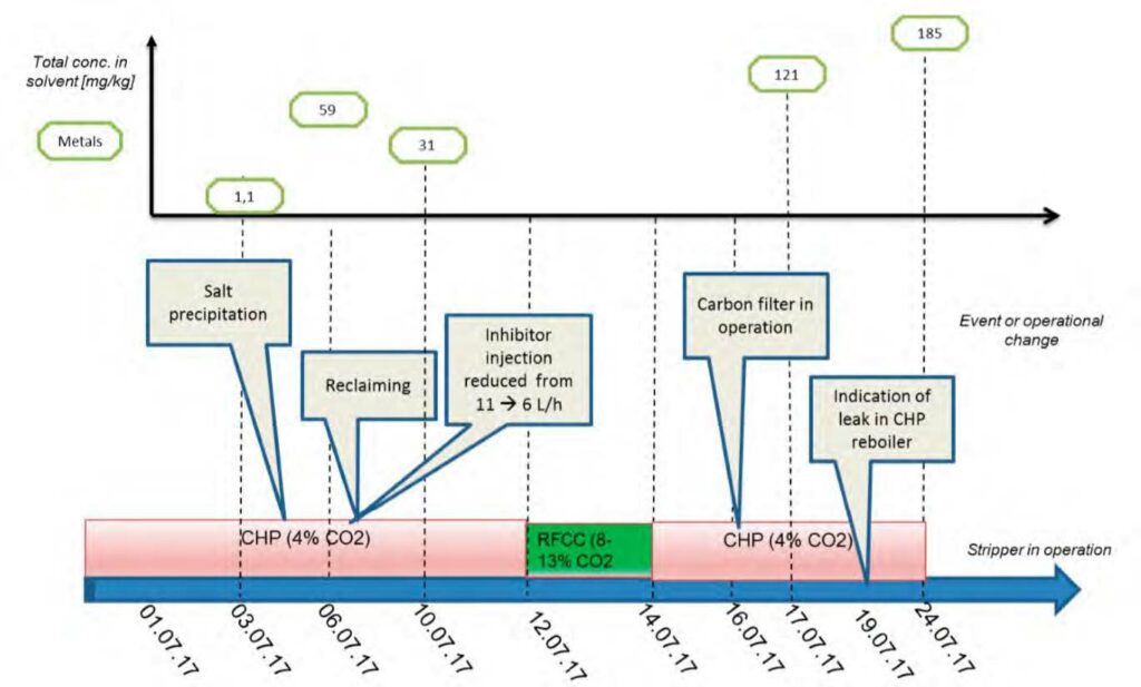
In 2017, TCM experienced severe corrosion in the CCGT (CHP) stripper reboiler shortly after starting a new monoethanolamine campaign named MEA-3. Before this test campaign, no signficantly signs of corrosion were observed in the process equipment since the amine facility was inaugurated in May 2012.
MEA-3 commenced on 9th of June 2017. The amine plant was thoroughly washed and flushed before the campaign started. At TCM, the metal content in amine solvents is analysed and monitored on a weekly basis (a minimum of once a week). During MEA-3, the first unusual increase of metals in the solvent was observed on 6th of July when the total metal content (Fe, Ni, Cr, Mo) reached 59 mg/kg, whereas the previous analysis on July 3rd only showed a total of 1.1 mg/kg metals. It is important to note that in only three days there was a sharp increase in dissolved metals, signifying the rapid development of metal dissolution. Such large number of dissolved metals was unprecedented at TCM. In the MEA-2 campaign in 2015, the maximum total metal concentration was 25 mg/kg (Mo was not even detected) and it happened at the end of the campaign after 77 days of continuous operations [11].
The detailed solvent analysis including degradation products, heat stable salts and metals along with process conditions for MEA-3 were presented previously [9,10]. The typical range of temperatures and flow velocities at the TCM amine plant are presented in Table 2. This is a low-pressure process where across the plant, pressure is about 1- 2 barg.
| Parameter | Hot lean solvent | Hot rich solvent | Cold lean solvent | Cold rich solvent | Stripper overhead vapor |
| Normal operating temperature [°C] | 120 | 110-115 | 30-55 | 35-50 | 90-100 |
| Max operating temperature [°C] | 123 | 118 | 72 | 70 | 117 |
| Phase | Liquid* | Liquid** | Liquid | Liquid | Vapor*** |
| Flow rate [ton/h] | 30-220 | 35-235 | 30-220 | 35-235 | 2.5-10 |
| Pipe size [inch] | 8 | 6 | 8 | 6 | 12 |
| Pipe flow velocity [m/s] | 0.3-1.9 | 0.5-3.6 | 0.3-1.9 | 0.5-3.6 | 4-18 |
Table 2. Typical range of temperatures and flow velocities at the TCM amine plant.
*The hot lean solvent might contain entrained bubbles from the desorption process.
** The hot rich solvent might flash in the lean/rich cross heat exchanger (two-phase flow is possible).
*** The stripper overhead vapor is at dewpoint and might contain droplets of condensed water.
4.3 The cause of corrosion incident
Given the vulnerability of MEA to oxidative degradation, potassium bisulfite (at 32 wt% aqueous solution strength) was used as an oxygen scavenger in the initial phase of MEA-3. The rate of injection was adjusted to keep a reasonable buffer of the scavenging agent (SO 2-) in the inventory i.e., 500-1000 mg/kg. The injection rate was kept at approximately 11 L/min.
On 6th to 7th July 2017, the solvent was reclaimed. The main purpose of reclaiming was to remove the large amount of sulfate accumulated in the amine at the time as the result of potassium bisulfite injection. At this point in time, the total sulfate/sulfite concentration was approximately 5 wt% i.e., very large salt concentration in the plant inventory. However, surprisingly the plant performance was intact until this point and hence normal operations were continued to observe the process performance as concentration of heat-stable salts increased in the solution. TCM advises against running the capture process at high heat-stable salt concentration. However, these tests created the opportunity to observe the adverse impact of accumulation of contaminants at a large-scale amine plant. The first alarming sign (observed on July 5th) was sudden salt precipitation in the cold lean solvent line including valves and sampling lines.
Operating with the MEA solvent was continued until first of July 2018. However, in this paper only the early period is discussed, where rapid changes in the plant situation led to detection of a leak in the CCGT (CHP) reboiler. Figure 1 is the graphic representation of this period. During this time, the plant was mostly run on CCGT flue gas containing 4% of CO2 except for the period shown in green where CO2 % was between 8% to 13%.
The analysis of 10th of July after the solvent was reclaimed showed 31 mg/kg of metals in the aqueous amine, suggesting that there was a reduction in metal concentration after reclaiming, as some metals are taken out of the amine circuit through reclaimer bottom sludge. One key learning of MEA-3 was to take samples before ending the reclaiming process to ensure that metal concentrations are reduced to the lowest achievable level. As a rule of thumb TCM advices removal of all metals down to detection limit. Failing to do so means that the remaining dissolved metals will potentially catalyse solvent degradation and thus corrosion mechanisms.
4.4 The Inspection
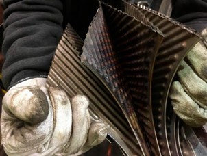
The entire amine plant was emptied, cleaned, and inspected just after the leak was detected but here, the focus is on the inspection of the leaking reboiler. After initial inhouse inspections at TCM’s mechanic workshop, the reboiler was sent to its supplier for further investigations. The CCGT (CHP) reboiler was a shell welded plate type heat exchanger. The schematics of the design is shown in Figure 2. The entire reboiler was made of 316 stainless-steel material.
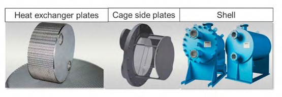
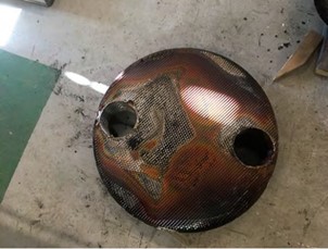
One leaking hole in the plates was leaking from the amine side. The welded plate stack where the leaking section was identified was cut. Figure 3 shows a significant layer of corrosion product deposits on the amine side of the plates. The leakage point was studied in more detail, and it was found that the defect formed on amine side was likely to be caused by flow induced corrosion/erosion.
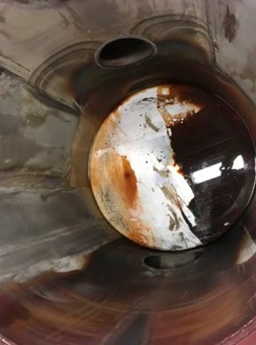
On the shell-side (Figure 4) deposits were observed within flow lines, and a pattern implying that the flow has not been uniform, indicating that some of the plates were plugged. Also, corrosion products were mainly observed on amine outlet (bottom part of Figure 4), whereas the inlet spool was relatively clean.
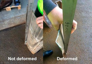
Cage-side plates were also inspected. Here, flow pattern corresponding to the pattern observed on the shell was found. Also, one of the plates suffered from substantial plastic deformation as shown in Figure 5. This deformation indicated abnormally high localized pressure from the inside of the cage, which again fits with the theory that heat exchanger plates were partially plugged. Subsequently, analysis of the corroded plates was performed at Equinor’s material laboratory in Porsgrunn, Norway. The morphology of the plates showed that on average the thickness was reduced by 200-250 µm in most of the surface, indicating general corrosion/erosion.
4.5 The Root Cause
Although various pathways were hypothesized as the cause for this severe corrosion incident, it was concluded that the most plausible pathway was the following:
Gaps between heat exchanger plates were partially filled with salts, solids, and precipitates. The amine flow was therefore restricted and maldistributed in the reboiler plates. Then, pressure increased locally inside the remaining passage causing plastic deformation of cage plates. Locally high wall shear stress in the remaining passage combined with presence of particles resulted in:
- Erosion of the oxide layer at surface of the 316L plates still exposed to amine
- Erosion and corrosion occurred to the 316L exposed plates (~ 200-250 µm corroded in average on the investigated plates)
- Erosion/corrosion was emphasized locally close to contact point between plates due to higher wall shear stress
- (At least) One leakage occurred due to this mechanism
Theoretically, austenitic stainless-steel type 316L is supposed to resist hot amines even in presence of bisulphites, sulphites, and sulphates. The reason is that it has a thin chrome oxide protective layer at its surface which protects it against corrosion. The corrosion protection of the material disappears if the chrome oxide layer is removed and if there is no oxygen to form it again. It was therefore assumed that the oxide layer was removed in presence of abrasive agents like particles. The use of oxygen scavenger prohibited any possible re-formation of the protective oxide layer. General corrosion then occurred on the 316L stainless steel plates.
4.6 Key Learnings
The TCM CHP reboiler failure due to corrosion demonstrates weakness of SS 316L for the (plate and frame) reboiler design at specific operational conditions when salt precipitation was observed in the plant. This does not necessarily indicate a general need for higher grade materials with more corrosion resistance for this equipment.
For the CHP reboiler, the amount of accumulated deposits over the years, was not known prior to the corrosion incident in 2017. However, the observations during subsequent plant inspections, showed that no or very limited corrosion had occurred on SS 316L test coupons localized close to the rebolier. The reboiler corrosion was therefore a very local phenomenon related to conditions that affected the reboiler plates only, which is supported by no other signs of corrosion detected on surrounding equipment or on the inlet/outlet pipelines.
TCM could not conclude if a more corrosion-resistant material exposed to the given conditions would stand the same conditions. But the overall conclusion was that failure would most likely avoided by maintaining the heat-stable salts concentration below the recommended level of 1.5 weight % reported by TCM elsewhere [10].
Reclaiming (amine purification) processes must be used to remove heat-stable salts, degradation products and dissolved metals; in short to maintain amine hygiene. Stringent solvent management (hygiene preservation) results in smooth operations, reduced amine loss and replacement, reduced heat exchanger fouling, reduced amine unit operating costs, fewer shutdowns and hence increased chance of meeting emission reduction targets.
5. Overview of emissions and environmental impact for different industries
At Technology Centre Mongstad (TCM) amine emission monitoring and abatement are of utmost importance. The aim is to ensure that the established TCM emission permit is respected and to develop learnings and a knowledge base which can be applied to commercial scale CCS projects. TCM is regulated under an emission permit from the Norwegian environmental authority (Miljødirektoratet). The emission permit regulates the amine plant’s emissions to air for ammonia (NH3), Amines (primary, secondary and tertiary) and aldehydes. Table 3 below shows the allowable emission limits applicable from the TCM amine plant.
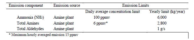
Table 3. TCM Amine plant applicable emission permit.
It is required that all amine solvents tested at TCM comply with the above emission permit, this is the case for open-source solvents, such as MEA and CESAR-1, but also for proprietary solvents. For each amine solvent tested at TCM, a rigorous assessment was needed to confirm safe levels of amine and amine degradation product emissions. The investigation included calculations for expected emissions from stack and appropriate atmospheric chemistry and dispersion modelling to ensure low impact on environment and immediate surroundings. The emission permit applicable for TCM amine plant is to allow TCM to tests different process parameters and process configuration, therefore this information in the table should be used with care as for a commercial scale plant the amine emission could potentially be stricter in terms of concentration (ppmv) of amine to air. It should be noted that TCM has an expert division which is responsible for emission permitting, atmospheric chemistry and dispersion modelling. If further information is needed to help define permits for commercial projects, TCM can provide direct support.
The main flue gas contaminant which signficantly impacts amine emissions to the stack is the concentration of total aerosol in the flue gas entering the absorber. Table 4 summarizes the difference in aerosol concentration for clean flue gas (CCGT) versus contaminated flue gas (RFCC). Depending on the industry of interest it is likely that the total aerosol concentration will lie somewhere between these two extremes. As can be seen the unfiltered RFCC flue gas has 300 to 500 times more aerosols as compared to the CCGT flue gas.
| Main parameters | Units | RFCC flue gas (unfiltered) | CCGT flue gas (unfiltered) |
| Number concentration | Part./cm3 | 15,000,000 – 25,000,000 | ~50,000 |
| Size distribution | mm | 0.01 to 10 | N/A |
| Weight concentration | Mg/Sm3 | 1,000 to 5,000 | N/A |
| Reference [12] |
Table 4. Aerosol concentration for TCM RFCC and CCGT flue gases.
After the above learning was made, TCM implemented an aerosol abatement option to ensure signficantly low levels of aerosols were entering the absorption column. The mitigation measure was a BDU (Brownian Demister Unit) installed upstream of the absorber column to ensure relatively clean flue gas enters the absorber. The amine emissions for RFCC flue gas test with the BDU filter are in the same order of magnitude of amine emission for the CCGT flue gas.
Table 5 summarizes the MEA emission results for testing on average at TCM for these two different flue gases. Notice the testing with RFCC flue gas (unfiltered) with no aerosol abatements was evaluated only for a short duration due to the high observed amine emission. As can be seen signficantly higher MEA emissions were observed for the RFCC (unfiltered) flue gas as compared to CCGT. It is likely that other contaminated flue gas sources can have similar impact of aerosols on amine emissions if no aerosol abatement is performed. After the above learning was made, TCM implemented an aerosol abatement option to ensure signficantly low levels of aerosols were entering the absorption column. The mitigation measure was a BDU (Brownian Demister Unit) installed upstream of the absorber column to ensure relatively clean flue gas enters the absorber. The amine emissions for RFCC flue gas test with the BDU filter are in the same order of magnitude of amine emission for the CCGT flue gas.
| Flue gas | MEA emissions (ppmv) | References |
| RFCC (unfiltered) | 20 to +100 | [13] |
| CCGT (unfiltered) | 0 to 0.4 | [14] |
| RFCC (with BDU filter) | 1 to 3 | [13] |
Table 5. MEA Emissions for TCM RFCC and CCGT flue gases.
In the design and planning phase for any CO2 capture project it will be necessary to understand the total aerosol concentration entering the absorption tower and to make sure appropriate aerosol abatement options are in place, otherwise emission permits will be breached. Also, it should be mentioned that standard water wash and acid wash section will not be effective in capturing amine emissions induced by aerosols. Different technology vendors may have different abatement options other than BDU, which is fine, however appropriate technology verifications should be made before implementing for full scale projects.
6. Conclusions
This paper provides information and recommendations that should be considered for any potential CO2 capture project. This includes projects developed for a wide range of CO2 intensive industrial applications, where typical data has been provided for inlet CO2 concentrations, CO2 emissions per year. Also, guidelines have been presented for the impact of CO2 capture on industrial production rates, plant layout, utilities and handling of amine-based solvents. Also, it has been shown how the impurities within a flue gas can signficantly impact amine-based solvent degradation/make-up and stack emissions. Several impurities were described and the two most impactful components NO2 and total particulates (aerosols) were highlighted. Experience and results have been shared for testing at TCM with clean flue gas (CCGT) and contaminated flue gas (RFCC). It can be concluded for any contaminated flue gas with a significant concentration of aerosols that proper gas cleaning/filtration will be needed, otherwise amine emissions would be too high, and regulators would not grant the necessary environmental permits. Lastly, an explanation has been given for the cause of a significant corrosion incident which has occurred at TCM during a Monoethanolamine (MEA) test campaign. A recommendation from this test campaign is to ensure solvent hygiene is of prime focus for any CO2 capture project. More specifically, to ensure a sufficient amine purification technology is available on site to maintain a sufficiently low steady state level of amine degradation products, salts and metals.
7. References
- European Commission, A Clean Planet for all – A European strategic long-term vision for a prosperous,modern, competitive and climate neutral economy. 2018: Brussels.
- IEA and CSI, Technology Roadmap – Low-Carbon Transition in the Cement Industry. Interntational Energy Agency (IEA) and Cement Sustainability Initiative (CSI). 2018
- Dietz, S., V. Jahn, and J. Noels, Carbon Performance Assessment of aluminium producers: note on methodology. 2019.
- Voldsund, M., et al., Comparison of Technologies for CO2 Capture from Cement Production—Part 1:Technical Evaluation. Energies, 2019. 12(3): p. 559.
- Roussanaly, S., et al., Towards improved cost evaluation of Carbon Capture and Storage from industry. Submitted to International Journal of Greenhouse Gas Control, 2020.
- S. Budinis, S. Krevor, N. Mac Dowellb, N. Brandon, A. Hawkes, An assessment of CCS costs, barriers and potential, Energy Strategy Reviews 22, 61-81. 2018.
- W.S. Amarasinghe, I. Husum, L.A. Tokheim, Waste heat availability in the raw meal department of a cement plant, Case Studies in Thermal Engineering 11, 1-142. 2018.
- P. Zakkour, G. Cook, CCS roadmap for industry: High-purity CO2 sources, Sectoral Assessment, CCS Industry Roadmap, Final Draft Sectoral Assessment, Carbon Counts (2010).
- N.E. Flø, L. Faramarzi, F. Iversen, E. R. Kleppe, B. Graver, H. N. Bryntesen, K. Johnsen, Assessment of material selection for the CO2 absorption process with aqueous MEA solution based on results from corrosion monitoring at Technology Centre Mongstad, International Journal of Greenhouse Gas Control 84 (2019) 91-110.
- A.K. Morken, S. Pedersen, S.O. Nesse, N.E. Flø, K. Johnsen, J.K. Feste, T. de Cazenove, L. Faramarzi, K. Vernstad, CO2 capture with monoethanolamine: Solvent management and environmental impacts during long term operation at the Technology Centre Mongstad (TCM), International Journal of Greenhouse Gas Control 82 (2019) 175-183.
- Flø N.E., Faramarzi L., de Cazenove T., Hvidsten O.A., Morken A.K., Hamborg E.S., Vernstad K., Watson G., Pedersen S., Cents T., Fostås B.F., Shah M.I., Lombardo G., Gjernes E., Results from MEA degradation and reclaiming processes at the CO2 Technology Centre Mongstad, Energy Procedia 114 ( 2017 ) 1307-1324.
- Lombardo et al, Results from testing of a Brownian diffusion filter for reducing the aerosol concentration in a residual fluidized catalytic cracker flue gas at the Technology Centre Mongstad – GHGT -14,2018.
- Shah et al, CO2 capture from RFCC flue gas with 30 wt % MEA at Technology Centre Mongstad, process optimization and performance comparison, GHGT-14.
- Morken et al, Emission results of amine plant operations from MEA testing at CO2 Technology Centre Mongstad, GHGT-12.