
14. Results from 30 wt% MEA performance testing at the CO2 Technology Centre Mongstad (2016)
Erik Gjernesa,*, Steinar Pedersenb, Toine Centsc, Guillaume Watsond, Berit F. Foståsb, Muhammad Ismail Shaha, Gerard Lombardoa,e, Coralie Desvignese, Nina Enaasen Fløe, Anne Kolstad Morkenb,e, Thomas de Cazenovee, Leila Faramarzib,e, Espen Steinseth Hamborgb,e
aGassnova SF, Dokkvegen 10, 3920 Porsgrunn, Norway bStatoil ASA, PO Box 8500, 4035 Stavanger, Norwa cSasol Technology, PO Box 5486, Johannesburg 2000, South Afric dShell Global Solutions International B.V., PO Box 663, 2501CR The Hague, The Netherlands eCO2 Technology Centre Mongstad (TCM DA), 5954 Mongstad, Norway *Corresponding author
(http://creativecommons.org/licenses/by-nc-nd/4.0/).
Peer-review under responsibility of the organizing committee of GHGT-13.
doi: 10.1016/j.egypro.2017.03.1276
Abstract

In 2015, the CO2 Technology Center Mongstad (TCM DA), operated a test campaign using aqueous monoethanolamine (MEA) solvent at 30 wt%. The main objective was to demonstrate and document the performance of the TCM DA Amine Plant located in Mongstad, Norway. The main elements were: verifying mass balances over the capture plant, revise the performance baseline from 2014, challenge the plant capacity, investigate mist/aerosol induced emission to the air and parameter variation in order to further stretch the plant performance. The current paper presents an overview of the campaign and reports on mass balance and plant performance.
1. Introduction
The CO2 Technology Centre Mongstad (TCM DA) is located next to the Statoil refinery in Mongstad, Norway. TCM DA is a joint venture set up by Gassnova representing the Norwegian state, Statoil, Shell, and Sasol. The facility run by TCM DA entered the operational phase in August 2012 and it is one of the largest post-combustion CO2 capture test centres in the world. A unique aspect of the facility is that either a flue gas slipstream from a natural gas turbine based combined heat and power (CHP) plant or an equivalent volumetric flow from a residual fluidized catalytic cracker (RFCC) unit can be used for CO2 capture. The CHP flue gas contains about 3.5% CO2 and the RFCC flue gas contains about 13-14% CO2. One of the main test plants at TCM DA is a highly flexible and well-instrumented amine plant. The amine plant was designed and constructed by Aker Solutions and Kværner to accommodate a variety of technologies, with capabilities of treating flue gas streams of up to 60,000 standard cubic meters per hour. The plant is being offered to vendors of solvent based CO2 capture technologies to, among others, test; (1) the performance of their solvent technology, and (2) technologies aimed to reduce the atmospheric emissions and environmental impact of amines and amine based degradation products from such solvent based CO2 capture processes. The objective of TCM DA is to test, verify, and demonstrate CO2 capture technologies suitable for deployment at full-scale. Up to now the vendors Aker Solutions, Alstom, Cansolv Technologies Inc. and Carbon Clean Solutions Ltd. have successfully used the TCM DA facilities to verify their CO2 capture technologies.
2. The 2015 MEA campaign
From July to October 2015 a test campaign capturing CO2 from flue gas from the CHP plant at Mongstad refinery was executed at TCM. The flue gas has typically 3.5% CO2 while the solvent comprised 30% aqueous monoethanolamine (MEA). The campaign was a joint project between TCM DA and its owners Gassnova, Statoil, Shell, and Sasol.
The campaign was split in five test series:
- Verify mass balances
- Revise the performance baseline
- Challenge the plant capacity
- Mist investigation
- Stretch targets
Series 1: The verification of the mass balances is described in section 4. The flow and composition measurements and methods for calculating total and CO2 mass balances are explained in detail and performance results are given. This test series (Series 1) was carried out at a flue gas flow rate of about 47,000 Sm3/h. Data collection was done under stable operating conditions and when the capture rate was 85%.
Series 2: The plant performance for operating conditions very similar to those reported from TCM in 2014 [1] was investigated with the new gas phase composition measurements that provided improved control of the mass balances. This test series (Series 2) used the stripper bottom temperature as the controlling variable and the solvent circulation rate was used to adjust capture rate as close as possible to 85% before experimental data was collected. The optimum performances for operation without and with the use of anti-foam were identified by the obtained u-curves, showing relation between the specific reboiler duty and the stripper bottom temperature or the lean loading. Results are given in section 5.
Series 3: The use of anti-foam improved significantly the plant performance. It also became clear that using anti- foam would allow stable plant operation at the full design flue gas flow plant capacity. Therefore a test series (Series
3) was run with 59,000 Sm3/h flue gas flow rate. The plant performance was documented according to the independent verification protocol (IVP) [2]. This new baseline is reported in [3] and will replace the TCM baseline published in 2014 [1]. Results from reducing absorber packing is, however, presented in section 6.
Series 4: A two week period of the campaign was used to investigate effect of mist/aerosol particles in the incoming flue gas on emissions to atmosphere (Series 4). This is reported in [4].
Series 5: The test series 5 (stretched targets) was planned to include tests with the use of lean vapor compressor (LVC, see bottom right corner of Figure 1), increased amine concentration (40%) and CO2 capture from flue gases at elevated CO2 concentrations. Due to time constraints, only the latter part of test series 5 was implemented. All tests were with the use of anti-foam and section 6 presents results from tests made from 3.6 to and 9 % CO2 in the flue gas flow into the absorber.
The total campaign included close to 2,000 hours of plant operation and results are reported in several papers that cover emissions and degradation [5], reclaiming [6] and corrosion [7].
Table 1 below presents an overview of the test series and main parameter ranges used during the 2015 MEA campaign at TCM.
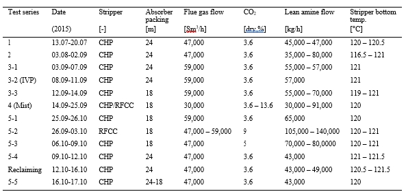
Table 1. Overall test activities with reference to tests series: 1 Verify mass balances, 2 Revise the performance baseline, 3 Challenge the plant capacity, 4 Mist investigation and 5 Stretch targets. Plant performance documented according to the independent verification protocol [2] is labeled 3-2 (IVP). The test series 5 covered variation in packing height and CO2 in flue gas into the absorber. At the end of the campaign, reclaiming was performed followed by two days of CO2 capture. The test series includes two weeks plant stop between test series 1 and 2 and a two days stop between test series 5-2- and 5-3. Stripper bottom pressure was typically maintained at around 0.95 barg.
3. The amine plant
The amine plant was designed and constructed by Aker Solutions and Kværner. It is a generic and highly flexible plant allowing testing at different configurations and with a wide range of flue gas compositions and flow rates. The process flow diagram is shown in Figure 1. The plant capacity is about 80 and 274 tonnes of CO2 per day for the CHP and RFCC flue gas operations respectively. The flue gas blower output capacity is up to about 270 mbar and 70,000 Sm3/h. The flue gas is cooled by a direct contact cooler with wash water. Water saturated flue gas flows upwards the rectangular cross-section absorber tower where it comes into contact with falling lean solvent solution. The absorber has three beds of structured packing and column packing heights can be 24, 18 or 12 m. Liquid distributors, liquid collector trays and mist eliminators are installed at various locations in the tower. The flue gas depleted in CO2 passes through two recirculating water wash stages before being emitted to the atmosphere. The process is operated with water balance. The water washes are used to control the depleted flue gas temperature and water content.
The CO2 rich solvent solution is pre-heated by exchange with hot lean solution and pumped to the upper part of a stripper tower. The rich solution falls down the stripper packing section and comes into contact with rising steam and released CO2. The lean solution is collected at the stripper bottom section and is circulated through a steam-heated thermosiphon reboiler system which provides the heat necessary to release the CO2. The lean solution is pumped back to the top of the absorber packing.
The amine plant has two independent stripper columns with overhead condenser systems. Both columns have a total height of 30 m. The structured packing internals are of 8 m height. One stripper is designed for the CHP flue gas and measures 1.3 m in diameter while the other stripper is 2.2 m in diameter. The second stripper is suited for higher flow capacities and is utilized when testing flue gases of higher CO2 content.
The CO2 product stream leaves the stripper and is cooled with recovery of condensate that is returned to the stripper as a reflux. The cooled CO2 stream is vented. When CHP flue gas is used it is possible to recycle a portion of the CO2 to the CHP flue gas upstream of the direct contact cooler. This allows for testing a range of CO2 concentrations in the inlet flue gas stream. More details on the plant design and equipment can be found in [1,2].
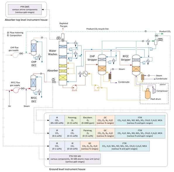
Figure 1. The TCM amine plant with two flue gas sources, CHP and RFCC, and the corresponding two strippers. Flue gas analyzers and flow meters are located at absorber inlet (I), outlet/depleted flue gas (II) and CO2 product (III), see also section 4, Table 2 and Table 3. The sets of IR meters for absorber in and out, IR CO2 (0 – 5 vol%)/IR CO2 (0 – 15 vol%) and IR CO2 (0 – 1 vol%)/IR CO2 (0 – 10 vol%) are referred to as IR-low and IR-high in Table 3. The dotted green line shows that CO2 can be recycled back to the absorber inlet for tests at elevated CO2 concentration in the flue gas flow.
4. Mass balance closure (Series 1)
The amine plant is planned and equipped for conducting research and development activities and in 2015 TCM completed implementation of a major upgrade of the gas phase composition measurement equipment. The original set up was with one common FTIR analyzer that in 90 minute cycle shifted between measuring each of the tree gas streams [1]. Figure 1 shows the new gas composition measurement setup that includes multiple gas composition analyzers at each gas stream providing continuous measurements. The CO2 measurements are based on fourier transform infrared spectroscopy (FTIR), infrared gas analysis (IR) and gas chromatography (GC). Absorber in and out have IR meters that cover both % and ppm range [3].
During the first part of the MEA 2015 test campaign the total- and CO2-mass balance of the amine plant was checked carefully. There are two meters for the inlet flue gas flow rate, one meter for the flue gas flow out of absorber and two meters for the CO2 product flow, see Table 2. The absorber out flue gas flow meter FT-2431 does not provide reliable measurements [1], thus flow out of absorber (V& ) is also calculated from flow into the absorber assuming all components except water (CH2O) and CO2 (CCO2) are conserved:
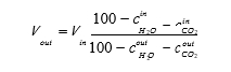
The mass balance is calculated as sum of absorber out and product flow divided by absorber in flow. This balance is based on 15 minutes averages of the measured gas flows in and out of the plant. No shift in time is applied, i.e. in order to take into account the residence time from gas phase absorber to gas phase stripper. Thus, stable operation is assumed. In Table 2 mass balance for four combinations of flow instruments, method A to D, are shown. Method A to C provide mass balances close to 100%. Method D which uses the absorber out pitot-based meter FT-2431 provides a mass balance around 95%, which suggests that this meter reports too low flow. For reference the CO2 concentration (dry) into the absorber is shown. Around July 14 the CHP changed firing mode which resulted in a decrease in the CO2 content in the flue gas and was stable for the rest of the week.
As shown in Figure 1 above there are four CO2 analysers at the absorber inlet and at the outlet and three analysers at the product stream. Based on method A to C in Table 2 the CO2 mass balance has been calculated using a combination of the CO2 analyzers. Table 3 shows the cases investigated. For A1, A2, B1 and C1 the gas composition out of stripper is assumed to be only CO2 and water were the latter is calculated from pressure and temperature assuming saturated conditions (f(T,p)). For A3 and A4 CO2 concentration is based on GC and FTIR measurements. All three methods give wet CO2 > 97 vol%.
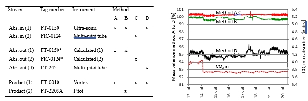
Table 2. To the left instrumentation for absorber in (Abs. in) and out (Abs. out) and product flow. The absorber out flow (1) and (2) are marked with asterisks since these flows are calculated from absorber in flows by use of equation 1. Mass balance based on four combinations of instruments, methods A to D, are presented for one week of operation in the figure to the right. CO2 concentration (dry) into the absorber is also shown.
The CO2 mass balance calculated as:
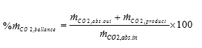
Figure 2 shows that method A1 to A4 and C1 results in CO2 mass balance within 100 +/- 5%. Method B1 which is based on the gas flow rates of method B has a larger spread and is underestimating the CO2 product flow resulting in an average CO2 mass balance around 90%. In conclusion all composition meters results in an acceptable CO2 mass balance, but flow should be based on method A or C.
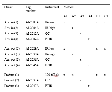
Table 3. Instruments for CO2 measurement at absorber in (Abs. in) and out (Abs. out) and product flow. With reference to Table 2 the measurements were combined with flow meters according to method A for four sets of instruments while method B and C were presented using the IR-low and CO2 product concentration by difference from calculated moisture (f(T,p)).
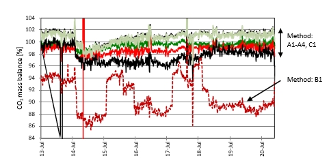
Figure 2. CO2 mass balance based on method A1 to A4, B1 and C1 in Table 3.
5. Performance (Series 2)
One of the objectives was to investigate the plant performance under the improved control of heat and mass balances as explained above. A key question from the 2014 baseline testing [1] was whether the CHP stripper was operated under optimal conditions. Indicators of poor stripper performance are; fluctuating temperature sensors, a radial temperature gradient, and a reduced temperature gradient over the packing section. This results in higher temperatures above the stripper packing, 100 to 102°C, as well as higher pressure drop over the stripper packing section. Reasons for this behaviour could be moderate foaming or maldistribution over the packing section of the upcoming steam and/or the down coming liquid solvent. TCM had some earlier experience that adding anti-foam to the solvent flow could improve the situation.
In industrial amine units, anti-foam chemicals are often injected when operators suspect foaming to occur in the columns, which can lead to large solvent carry-over to the downstream overhead units. This could result in production turn down or worse, unplanned shutdown. The increase or rapid fluctuation of pressure drop over the amine column, and the unexpected level change in the amine unit (with rapid change of the control valve) are general indicators for foaming. Note that such foaming event in the TCM facility was likely not experienced during the campaign, and that the columns were operating within their design hydraulic operating window (i.e. no flooding).
This part of the test campaign repeated conditions from the 2014 tests at TCM [1] and included operation with and without the use of anti-foam. The main parameters used for creating u-curves and determining the optimum steam reboiler duty (SRD) under series 2 are given in Table 1 above. The tests were run at stable conditions with CO2 inlet concentration about 3.6 vol %, dry. The stripper bottom pressure was held constant at 0.95 barg. The stripper bottom temperature was used as the controlling variable. For each selected temperature one point on the u-curve was created. The solvent flow rate was used to tune in the capture rate as close as possible to 85% at each test temperature before data collection.
The data for u-curves were prepared as shown in Figure 3 below. At a set stripper bottom temperature the lean solvent flow was tuned in order to achieve 85% capture rate. Rich and lean solvent was sampled during stable operation. Rich and lean loading data were obtained. The rich loading were always close to the equilibrium value of 0.50 mole CO2/mole amine while the lean loading responded closely to the set stripper bottom temperature. The solvent flow rate was reduced in corresponding steps with the lean loading.
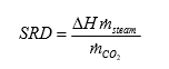
The test series started without the use of anti-foam. The main performance parameters are shown in Table 4 below. The SRD value is calculated based on the difference in steam enthalpy (ΔH) over the reboiler, the steam mass flow (ṁsteam) and mass flow of CO2 out of the product line (ṁCO2):
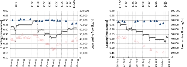
Figure 3. To the left tests without anti-foam and to the right tests with the use of anti-foam. Lean and rich loading are shown as filled blue and open red triangles, respectively. Lean amine flow (black points) is adjusted to get approximatively 85% CO2 capture and then kept constant at each level of stripper bottom temperature. The latter is indicated as vertical dotted lines.
The CO2 capture rate is calculated based on a simplified expression using CO2 concentration in and out of the absorber:
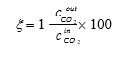
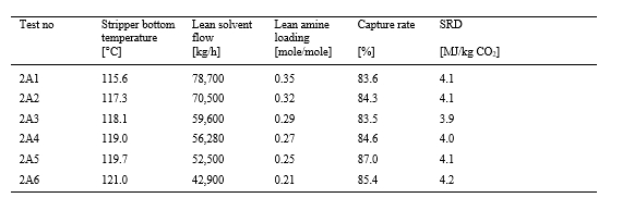
Table 4. Results for test cases without the use of anti-foam. The use of “A” and “B” (Test no) in Table 4 and Table 5 identifies tests without and with anti-foam, respectively. Loading is reported as mole CO2/mole amine.
The stripper performance was observed by following the temperature profiles over the stripper packing section, the pressure drop over the packing and the temperature sensor placed above the stripper packing. All the indicators showed that the stripper was not performing optimal and therefore the anti-foam injection was decided. At August 26 four litre of anti-foam was added. After anti-foam had been injected all the indicators showed good stripper performance. The test series were continued in order to create a u-curve and determine optimum SRD value also for operation with the use of anti-foam. The strategy was to inject one litre of anti-foam if the indicators again showed signs of undesired behaviour to secure optimal performance for all the points on the u-curve. Figure 4 below illustrates how this operation was managed for the whole test series.
The most important performance parameters for the test cases with the use of anti-foam are shown in Table 5 below.
Data from Table 4 and Table 5 were used to create the u-curves shown in Figure 5 below.
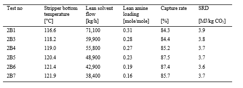
Table 5. Results for test cases with the use of anti-foam. The use of “A” and “B” (Test no) in Table 4 and Table 5 identifies tests without and with anti-foam, respectively. Loading is reported as mole CO2/mole amine.
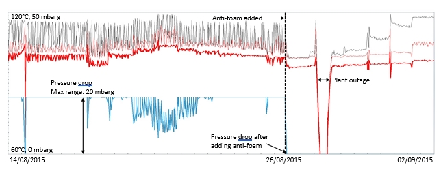
Figure 4. Stripper performance and result of using anti-foam is shown for the whole test series 2, see Table 1.The dashed vertical line shows the first use of anti-foam August 26 2015. The upper black and red thin lines show temperature sensors inside the stripper packing. The bold red and blue lines are temperature above the stripper packing and pressure drop over the stripper packing, respectively. Note that before adding anti-foam the pressure drop exceeded max range of 20 mbarg for the meter. Anti-foam resulted in immediate stabilising of temperatures and reduced the pressure drop over stripper. The further drop in temperature to the right of this is due to a short plant outage.
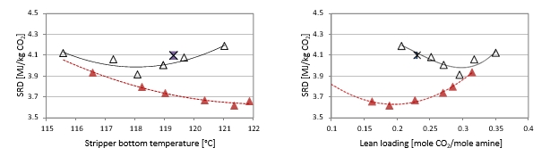
Figure 5. U-curves from series 2 and operation with anti-foam are shown as red filled triangles while results without the use of anti-foam are shown as open triangles. To the left SRD is given as function of stripper bottom temperature. To the right SRD is given as function of lean loading. The asterisk represents the 2014 baseline [1] made without the use of anti-foam.
The significant effect of anti-foam is clearly seen from the graphs. The stripper behaviour becomes much more optimal and the heat is no longer lost through the stripper overhead but used in efficient release of the CO2 from the solvent amine. This leads to significantly lower specific reboiler duty and the optimum operation is shifted towards much leaner amine and less solvent circulation.
During test series 3 the independent verification protocol (IVP) and the 3rd party measurements were documented. Since the use of anti-foam allowed stable plant operation also at the full flue gas design capacity this operating condition was chosen for the verification testing, see series 3-1 (IVP) in Table 1. This test series established at 59,000 Sm3/h flue gas flow will replace the baseline published in 2014 [1] and is reported in [3]. In Table 6 the main characteristics for the 2014 baseline are compared with test results from series 2. These tests were conducted at about the same flue gas flow of 47,000 Sm3/h, CO2 below 4 vol.% and with 24 meters of absorber packing. For comparison the table includes test “2A5” that have similar parameters as the 2014 baseline. The cases “2A3” and “2B6” represent optimum energy performance for operation without and with the use of anti-foam, see also Figure 5 above. The use of anti-foam gave about 20% reduction in lean amine flow rate and 12% reduction in SRD compared to the 2014 baseline.
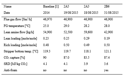
Table 6. Comparison of the 2014 baseline and results from optimal performance testing. All tests are with 24 m absorber packing and around 3.6% dry CO2 in flue gas from the CHP. Data sets “2A5” and “2A3” are without the use of anti-foam and are taken from Table 4, while “2B6” is with anti-foam and data are taken from Table 5. Loading is reported as mole CO2/mole amine.
6. Parameter variations (Series 3 and 5)
The test series 3 and 5 included tests made with 18 m absorber packing height and also tests at elevated CO2 concentration in the flue gas flow into the absorber. These parameter variations will be discussed below.
With a new baseline established for full flue gas flow capacity (59,000 Sm3/h) and use of 24 m absorber packing height [3] it was suggested to challenge the plant capacity even further with a test series at 18 m packing height. The flue gas flow rate was fixed at 59,000 Sm3/h and anti-foam was injected prior to the tests if needed. These results are presented in Table 7. In case “3A3” the absorber packing height was reduced from 24 to 18 m. The SRD value increased and rich loading decreased from 0.48 to 0.46, indicating that 18 m is not sufficient to give equilibrium. In case “3A4” the stripper bottom temperature was decreased from 121 to 119°C, resulting in a corresponding increase in lean loading from 0.20 to 0.26 and the capture rate decreased from 83 to 68%. In case “3A7” the stripper bottom temperature was increased to 120°C giving a lean loading of 0.23 and capture rate 76%. In case “3A8” the target was to achieve 85% capture rate at 120°C by changing the lean solvent flow rate. An increase in flow rate from 59,000 to 67,700 kg/h was required. For all these parameter variations the SRD was 3.6 to 3.9 MJ/kg CO2.
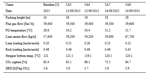
Table 7. Parameter testing with 18m packing height compared to the new baseline (all with anti-foam). Loading is give as mole CO2/mole amine.
Test series 5 also included tests at elevated CO2 concentrations. The test series 5-2 and 5-3 started at stable conditions with 18 m packing height, flue gas flow 46,200 Sm3/h and stripper bottom temperature 120.5°C. The objective was to investigate performance with increased CO2 flue gas inlet concentration. At TCM the CO2 inlet concentration can be varied by recycling CO2 from the CO2 product vent and back into the incoming flue gas. The CO2 concentration was varied in controlled steps between nine and three percent (wet). The capture rate was kept close to 85% by adjusting the parameters stripper bottom temperature and lean solvent flow rate. The observed effects on SRD and solvent loading are shown in Figure 6 below.
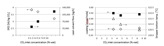
Figure 6. To the left SRD (diamonds) and lean solvent flow rate (squares) observed as function of inlet CO2 concentration. To the right lean (diamonds) and rich (squares) solvent loading and stripper bottom temperature (triangles) observed as function of inlet CO2 concentration.
The testing started with CO2 concentration about 9 % wet and lean solvent flow 120,000 kg/h. The amount of captured CO2 was 7,500 kg/h. When the CO2 concentration was reduced to about 5% wet the lean solvent circulation was correspondingly reduced to 70,000 kg/h to reach 85% capture rate and the resulting amount of CO2 captured was 3,900 kg/h. The baseline conditions were then tested with 3.6 % wet CO2 inlet concentration. The CO2 captured was 2,700 kg/h.
The capture rate was within the range 85 to 88% for all the three selected test cases. From the right panel in Figure 6 it is seen that the stripper bottom temperature was only slightly adjusted between 120.5 and 121.5°C giving some minor changes in rich and lean loading.
As expected, the SRD increased with decreasing CO2 inlet concentrations. It is interesting to further investigate the trade-off between CAPEX and OPEX parameters for operating conditions relevant for various gas power turbines and exhaust gas recycling systems in order to assess how total capture cost can be minimized.
7. Conclusion
The MEA 2015 campaign at TCM has provided a verification of mass balance over the plant and shown that the CO2 mass balance based on gas phase can be maintained at a level better than +/- 5%. The plant performance presented in 2014 [1] has been revisited under operation with and without the use of anti-foam. Use of anti-foam enabled stable operation at lower lean solvent loading which resulted in lower lean amine flow rate and reduced SRD. Absorber packing height has been challenged and the results points towards operation at lower packing heights, but current tests also indicated that equilibrium was not achieved at reduced packing height. Tests at elevated CO2 concentration showed as expected reduced SRD with increasing CO2 concentration. The campaign has also resulted in reports on: new baseline [3], mist/aerosol induced emission to the air [4], emissions and degradation [5], reclaiming [6] and corrosion [7].
Acknowledgements
The authors gratefully acknowledge the staff of TCM DA, Gassnova, Statoil, Shell and Sasol for their contribution and work at the TCM DA facility. The authors also gratefully acknowledge Gassnova, Statoil, Shell, and Sasol as the owners of TCM DA for their financial support and contributions.
References
- Hamborg ES, Smith V, Cents T, Brigman N, Falk-Pedersen O, de Cazenove T, Chhaganl M, Feste JK, Ullestad Ø, Ulvatn H, Gorset O, Askestad I, Gram LK, Fostås BF, Shah MI, Maxson A, Thimsen D. Results from MEA testing at the CO2 Technology Centre Mongstad. Part II: Verification of baseline results. Energy Procedia. Volume 63; 2014. p. 5994-6011.
- Thimsen D, Maxson A, Smith V, Cents T, Falk-Pedersen O, Gorset O, Hamborg ES. Results from MEA testing at the CO2 Technology Centre Mongstad. Part I: Post-Combustion CO2 capture testing methodology. Energy Procedia, Volume 63; 2014. p. 5938-5958.
- Faramarzi L, Thimsen D, Hume S, Maxson A, Watson G, Pedersen S, Gjernes E, Fostås BF, Lombardo G, Cents T, Morken AK, Shah MI, de Cazenove T, Hamborg ES. Results from MEA testing at the CO2 Technology Centre Mongstad: Verification of baseline results in 2015. Energy Procedia (GHGT-13), Forthcoming 2017.
- Lombardo G, Fostås BF, Shah MI, Morken AK, Hvidsten OA, Mertens J, Hamborg ES. Results from aerosol measurement in amine plant treating gas turbine and residual fluidized catalytic cracker flue gases at the CO2 Technology Centre Mongstad. Energy Procedia (GHGT- 13), Forthcoming 2017.
- Morken AK, Pedersen S, Kleppe ER, Wisthaler A, Vernstad K, Ullestad Ø, Flø NE, Faramarzi L, Hamborg ES. Degradation and Emission Results of Amine Plant Operations from MEA Testing at the CO2 Technology Centre Mongstad. Energy Procedia (GHGT-13), Forthcoming 2017.
- Flø NE, Faramarzi L, de Cazenove T, Hvidsten OA, Morken AK, Hamborg ES, Vernstad K, Watson G, Pedersen S, Cents T, Fostås BF, Shah MI, Lombardo G, Gjernes E. Results from MEA degradation and reclaiming processes at the CO2 Technology Centre Mongstad. Energy Procedia (GHGT-13), Forthcoming 2017.
- Hjelmaas S, Storheim E, Flø NE, Thorjussen ES, Morken AK, Faramarzi L, de Cazenove T, Hamborg ES. Results from MEA amine plant corrosion processes at the CO2 Technology Centre Mongstad. Energy Procedia (GHGT-13), Forthcoming 2017.