
13. CO2 product quality: assessment of the range and level of impurities in the CO2 product stream from MEA testing at the Technology Centre Mongstad (TCM) (2018)
Kim Johnsena,b, * , Eirik Romslo Kleppea, Leila Faramarzia,b, Christophe Benqueta,d, Erik Gjernesc, Gelein de Koeijerb, Thomas de Cazenovea, Anne Kolstad Morkena,b, Nina Enaasen Fløa, Muhammad Ismail Shaha,c, Magnus Aronssona, Øyvind Ullestada
aTechnology Centre Mongstad, 5954 Mongstad, Norway bEquinor ASA, PO Box 8500, 4035 Stavanger, Norway cGassnova SF, Dokkveien 10, 3920 Porsgrunn, Norway dTotal E&P Norge, Finnestadveien 44, Dusavik, 4029 Stavanger, Norway
Abstract

During the recent MEA campaign at the Technology Centre Mongstad (TCM), a broad range of operational conditions have been explored for the post-combustion amine-based CO2 capture demonstration plant. This paper presents CO2 product composition data from online gas analyzers, originating from CO2 capture of two different flue gas sources available at TCM. Detailed composition data obtained by manual sampling and laboratory analysis, both internally at TCM and by Airborne Labs International Inc. is presented. Among the impurities identified and analyzed for, ammonia, formaldehyde and acetaldehyde are the compounds not commonly reported in the literature. The solvent quality, in terms of metal content and amount of degradation products, seemed to be the most influential parameter affecting the concentration of acetaldehyde and ammonia in the CO2 product gas. In addition, ammonia slip was found to be correlated with operating temperature of the overhead stripper system.
1. Introduction
1.1 MEA campaign at TCM
The Technology Centre Mongstad (TCM) is the world’s leading facility for verifying and improving CO2 capture technologies. TCM is located at Mongstad, one of Norway´s most complex industrial facilities. TCM has been operating since autumn 2012, providing an arena for qualification of CO2 capture technologies on an industrial scale. In autumn 2017, Gassnova (on behalf of the Norwegian state), Equinor (formerly Statoil), Shell and Total entered into a new ownership agreement securing operations at TCM until 2020. The owners of TCM started their most recent monoethanolamine (MEA) test campaign in June 2017 where a large number of public, industrial, research and academic stakeholders were involved [1]. The campaign included demonstration of a model-based control system, dynamic operation of the amine plant, investigating amine aerosol emissions and specific tests targeted at reducing the cost of CO2 avoided. Through the testing, both flue gas sources currently available at TCM were used. These sources are the combined cycle gas turbine (CCGT) based heat and power plant (CHP) and the residual fluid catalytic cracker (RFCC). They provide flue gases with a wide range of properties and a CO2 content from 3.6 to 14%. TCM is located next to the Equinor refinery in Mongstad. The Mongstad refinery is the source of both flue gases supplied to TCM. One of the objectives of the campaign has been to characterize the CO2 product gas, which is presented in this paper.
1.2 Knowledge gaps
The compounds that make up the CO2 product stream from a CO2 capture plant can generally be grouped by their impact on the integrity of downstream transport- and storage systems, health and safety issues or cost impact on overall carbon capture and storage (CCS) value chain. There are several literature references [2,3,4,5,6] discussing the concentration range of compounds expected from the main capture technologies used with fossil-fueled power plants or other industrial sources. The most commonly reported impurities for post-combustion capture technologies, along with their impact on CCS value chain, are listed in Table 1.
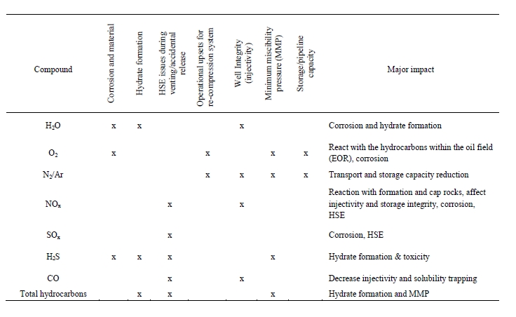
Table 1: Reported impact of CO2 product composition on compression system, transport and storage (incl. EOR) [2-6].
References with actual product CO2 composition data from large scale pilots or demonstration plants operated with amines are rather sparse. In particular, the concentrations of impurities such as amines, ammonia and aldehydes are not easily accessible in the open source literature, although some operational data have previously been reported by TCM during the 2015 MEA baseline tests [7]. Aldehydes, as a possible human carcinogenic by-product of MEA degradation, may represent a HSE risk for CCS facilities if present in high concentrations. Occupational exposure limits are presented by Gentry et al. [8] for both formaldehyde and acetaldehyde. For example, the Health and Safety Executive in the UK has put a long-term exposure limit of 2 and 20 ppm for formaldehyde and acetaldehyde respectively.
The CO2 product gas composition is likely to vary, depending on plant design, operational parameters and solvent properties. During the recent MEA campaign at TCM, a broad range of operational conditions have been explored for the amine plant. This paper presents CO2 product composition data from the online gas analyzers installed at TCM, originating from CO2 capture of both flue gas sources available. Moreover, detailed composition data obtained by manual sampling and laboratory analysis, both internally at TCM and by external labs (Airborne Labs International, Inc.) is presented. The assessment of the CO2 product composition in this work covers the following operational aspects and sensitivities:
- Composition data from both flue gas sources at TCM;
- Solvent quality;
- Stripper overhead system operation;
- Transient operation.
2. Instrumentation and sampling
2.1 TCM amine plant instrumentation
The major constituents of the CO2 product stream are measured by different online analyzers (FTIR/GC/IR) downstream the stripper overhead receiver, as shown in Figure 1. In addition, a manual sampling point is located adjacent to the analyzer off-take, enabling sampling and identifications of additional trace compounds. In the 2015 MEA campaign [7] the manual sampling was performed closer to the CO2 vent stack, and located further downstream of the new sample point, with a larger risk of condensation and non-representative sampling.
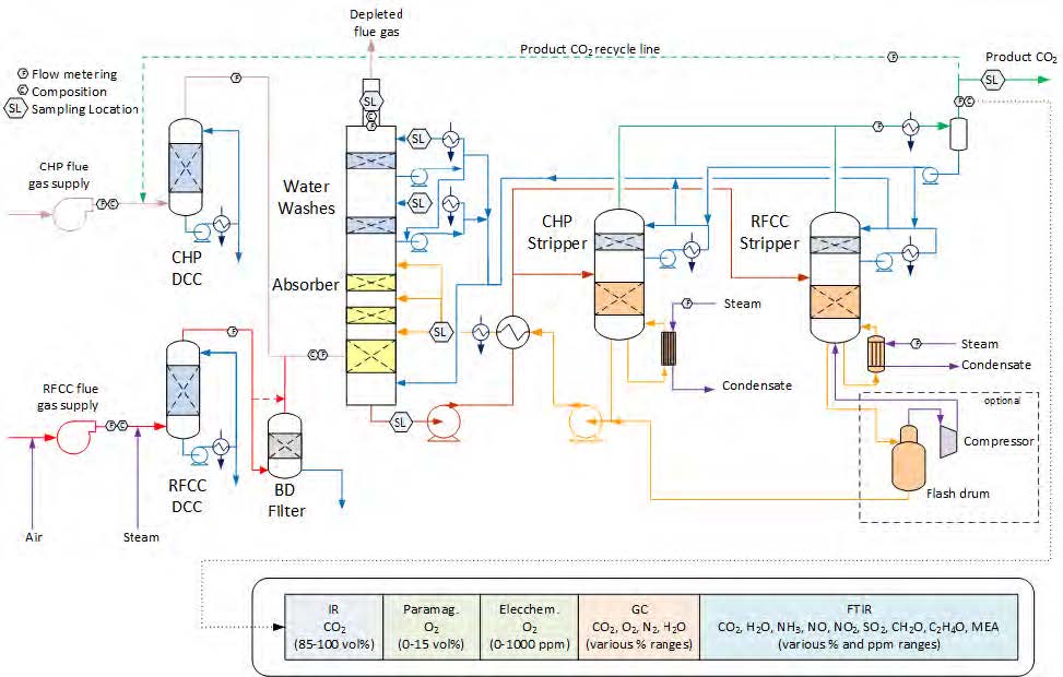
Figure 1: Schematic drawing of TCM amine plant and CO2 product analysis location.
At TCM there are two dedicated strippers for operation with each of the flue gas sources containing different CO2 concentration levels. Both strippers are equipped with a water wash circulation system in addition to the reflux, as shown in the schematic above. The purpose is to “polish” the gas, reducing traces of soluble impurities in the CO2 rich gas leaving the stripper. When the stripper water wash system is not in operation, only the reflux from the overhead condenser drum is returned to the stripper.
2.2 Airborne Labs analysis
CO2 product gas analysis was done by Airborne Labs International, which is an accredited ISO/IEC 17025 laboratory and provider of analytical chemistry testing involving high purity gases and other types of gaseous samples. Sampling was performed during two periods of MEA campaign in 2017 for both flue gas sources. The sampling was done by TCM lab personnel as instructed by the sample kits provided by Airborne Labs. The complete list of compounds analyzed for by Airborne Labs, including analysis method and uncertainty of analytic readings, is found in Appendix A.
3. Detailed composition data
3.1 Composition data from CHP and RFCC flue gas testing
The CO2 product gas sampling was conducted at two different time slots during the MEA campaign, operated with CHP and RFCC flue gas respectively. Table 2 shows typical flue gas conditions upstream the absorber at TCM.
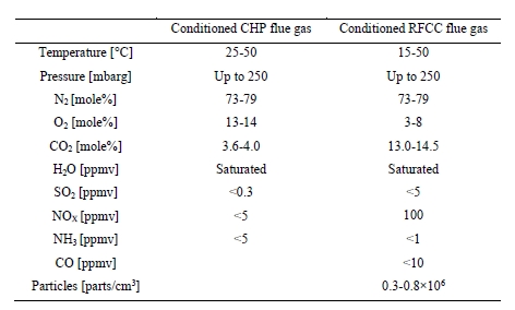
Table 2: Typical CHP and RFCC flue gas conditions upstream absorber.
The results from the detailed analysis from Airborne Labs are presented in Table 3. Compounds analyzed for, but not detected are not included the table (the complete list of compounds analyzed for is found in Appendix A). However, some selected impurities of particular interest for CCS, are still reported as not detected (Nd) in the table for the records. The concentrations are reported on an as-is wet basis, except for CO2 which is on a dry basis.
Three kits for each flue gas source were used during sampling. However, the gas cylinders for two of the sample kits used during the CHP campaign were reported to contain high levels of oxygen and nitrogen, indicating that air contamination may have occurred during the sampling process. Hence, these results are considered to be non- representative and concentrations of CO2 and non-condensables are not reported for these samples. It should be noted that in the period between the CHP and RFCC campaigns the sample probe was somewhat modified to reduce the risk of condensation in the sample probe.
Table 3 also lists some key operational process parameters during the sampling periods. Solvent quality in terms of metal content and degradation products during the campaign is reported elsewhere [9]. The first product gas sampling during the CHP flue gas campaign in June was performed only one week after the start-up of the amine plant, whereas the two last CHP samples were taken four weeks after the start-up. Sampling with the RFCC flue gas was done over a period of two weeks, four and five weeks after a thermal reclaiming campaign respectively. The impact of solvent quality on the product gas quality is also discussed later in this paper.
A Brownian diffusion (BD) filter is installed downstream the RFCC direct contact cooler (DCC), to control the particle concentration in the RFCC flue gas entering the absorber. A by-pass line is also provided to allow for testing at varying particle concentrations, and sampling was performed both for closed and partly open by-pass line during the RFCC testing. Lombardo et al. [10] provide details on the nature of the aerosols particles and removal efficiency of the Brownian diffusion filter.
The stripper overhead system was operated without the dedicated stripper water wash in operation, i.e. only reflux water returned to the upper stripper packing wash section, throughout all sampling periods.
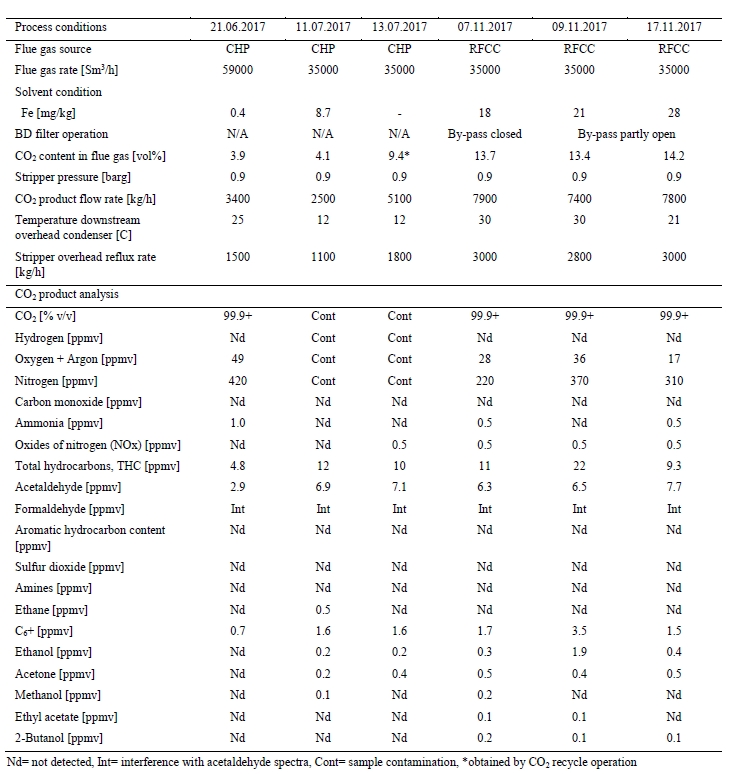
Table 3: Results from detailed CO2 product composition analysis by Airborne Labs.
3.2 Comparison with online instrumentation
A comparison of the Airborne analysis results with TCM online instrumentation is provided in Table 4 for two selected periods, running with CHP and RFCC flue gas, respectively. For some of the compounds there were additional manual samples and analysis performed by the TCM lab, as noted in the table.
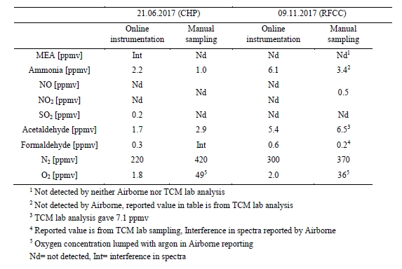
Table 3: Results from detailed CO2 product composition analysis by Airborne Labs.
Neither the online instrumentation nor the analysis from manual sampling could quantify any amines from the CO2 product gas in the selected periods of comparison. There is fairly good agreement for NOx and SO2 between the online FTIR and analysis by Airborne Labs. Moreover, nitrogen concentrations are also comparable, whereas the online electrochemical measurement for oxygen is significantly lower than reported by Airborne Labs. However, these oxygen results are not directly comparable, as Argon is lumped into the reported oxygen concentration from Airborne. For ammonia, the online FTIR is showing higher values than both analysis performed by Airborne Labs or by the TCM lab. Based on a comparison of a series of ammonia analysis done by the TCM lab throughout the MEA-3 campaign at different point in time, these manual samples are rather consistently and systematically showing approximately 50% of the concentrations found by the FTIR.
For aldehydes the concentrations measured by the FTIR are comparable with manual sampling. Figure 2 shows FTIR measurement of formaldehyde and acetaldehydes in the period of 7th to 9th of November. The results from manual sampling and analysis by Airborne and TCM lab, respectively, are included in the figure.
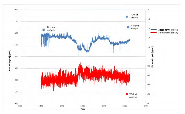
Figure 2: Online FTIR measurement of aldehydes, compared to results from manual sampling and analysis by Airborne TCM/SINTEF for 7th and 9th of November.
4. CO2 product composition sensitivities
4.1 Stripper overhead condensing temperature
The CO2 product is cooled down in the overhead condenser. The condensed vapor is collected in a reflux receiver drum and returned to the stripper as cold reflux over the upper water wash packing section, as shown in Figure 1. At TCM the CO2 stripper is also equipped with a stripper water wash circulation system in addition to the reflux. The operational mode of the overhead system will influence the CO2 quality. In particular, the effect of the condensing temperature and total reflux rate, is of interest with respect to traces and impurities in the CO2 product stream.
A test with CHP flue gas was performed, where the cooling duty of the condenser was reduced in steps, and consequently increasing the CO2 product temperature downstream the condenser from 18 to 25 and 35°C in a step- wise manner. The reflux rate was kept stable during the ramps, without operation of the dedicated stripper water wash system. With increased temperature, the water content in the CO2 product is increased, as an obvious consequence. More interestingly, it was observed that ammonia emissions increased from a steady value of 3 ppmv to almost 6 ppmv, for a condenser outlet temperature of 18 and 35°C, respectively. Reducing the temperature back to 18°C, restored the approximate same concentration of ammonia as prior to the temperature ramp-up, as seen in Figure 3.
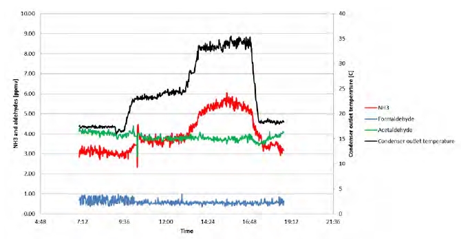
Figure 3: Ammonia and aldehydes concentrations during temperature change of CO2 product gas.
Increasing the CO2 product temperature will increase the vapor pressure of dissolved ammonium causing higher ammonia slip to downstream re-compression systems and transport system. Also shown in Figure 3 are the formaldehyde and acetaldehyde concentrations, which were not significantly influenced by the temperature changes.
The online FTIR did not detect any amines in the CO2 product gas for the temperature interval explored during this ramp test.
4.2 Solvent quality
During the MEA campaign both solvent reclaiming and partial or complete inventory replacement have been done to maintain good solvent condition. For certain periods of the campaign the solvent metal content has been higher than usual, as described by Morken et al. [9]. Two selected periods with aged and fresh solvent, denoted F and G respectively, have been assessed for any observable changes in the CO2 product composition. In period F, the solvent contained relatively high concentrations of metals and degradation products, whereas period G represents a period after a complete solvent inventory replacement and plant wash. More details on the solvent condition in these periods are described elsewhere [9]. For both periods the capture plant was operated with the CHP flue gas. Some key operating conditions for a selected 12-hours window within both periods are listed in Table 5 along with average values for generation of iron, heat stable salts and D-mix.
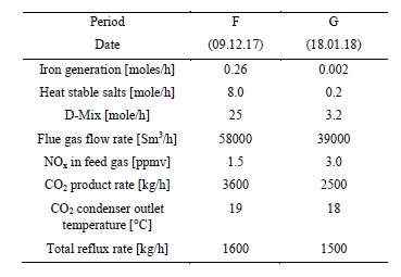
Table 5: Key operational parameters for comparing CO2 product impurities for two periods.
Figure 4 shows how ammonia and acetaldehyde in the CO2 product gas compare for a selected time interval of 12 hours in the two periods. Data points every minute are shown. First, it is evident that the ammonia concentration is significantly higher for period F than G, with concentrations in the region of 50-60 ppmv. This relates to the difference in metal concentration in the solvent for the two periods, as iron has an increased catalytic effect on oxidative degradation of the solvent, resulting in higher ammonia emissions. Also, it is seen that the concentration of acetaldehyde is significantly higher for period F with average of 16 ppmv, compared to approximately 2 ppm for period G. The concentration of formaldehyde, not shown in the figure, does not seem to be correlated to solvent conditions in the same way as acetaldehyde, as both periods show values in the same range of concentrations. Unfortunately, reliable readings of amines from the online FTIR was not available for both the periods under consideration.
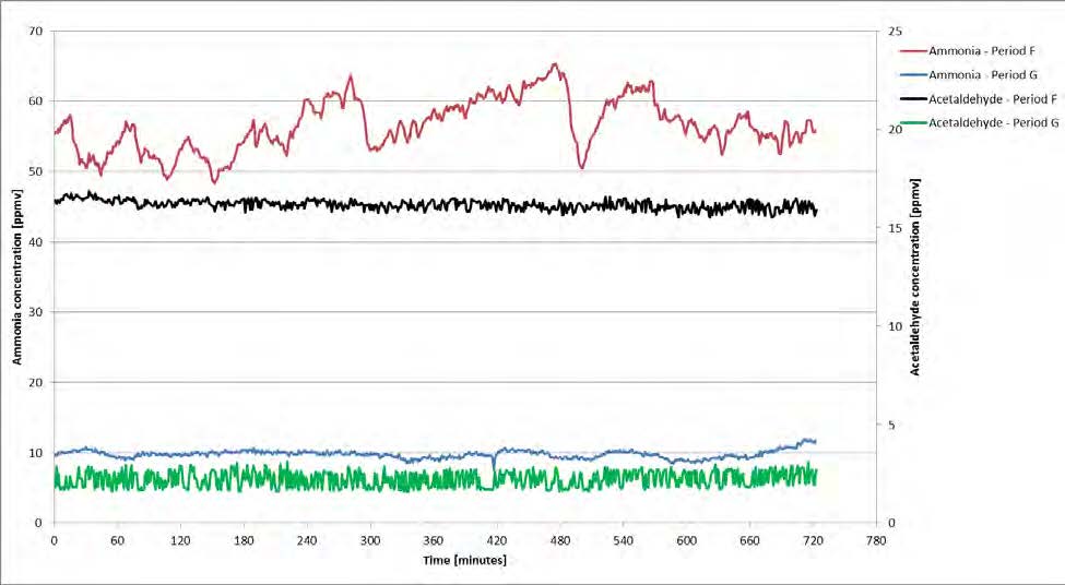
Figure 4: Ammonia and acetaldehyde concentrations (FTIR) in CO2 product over a 12-hours period for periods F and G. Data points averaged every minute.
4.3 Transient operation
A so-called rapid load change test was done by ramping the CHP flue gas rate between 55000 Sm3/h to 35000 Sm3/h within 5 minutes, while adjusting solvent circulation rate and reboiler duty to maintain a constant capture rate of approximately 85%. Figure 5 shows the corresponding solvent circulation and CO2 product flow rates for this test. This test intended to mimic a rapid load change/turn down of the power plant, to study if there were any observable changes in the CO2 product composition.
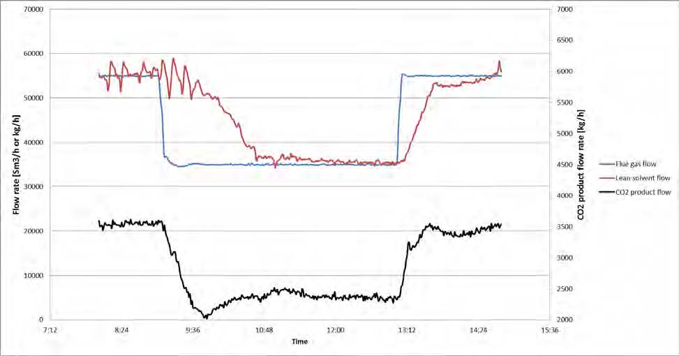
Figure 5: Flow rates of flue gas (CHP), solvent and product gas for transient rapid load change test.
For the ramp-down, the stripper outlet temperature is slightly increased during the transient as the total product flow rate decreases, reducing the required cooling duty of the overhead condenser. As the condenser temperature controller was not properly tuned for such a transient, this resulted in a slight increase in CO2 product temperature and hence ammonia slip, as a seen in Figure 6. The aldehydes concentrations are rather stable during the transients, except for a small peak in acetaldehyde concentration observed during the ramp-up. There was not detected any MEA, NOX or SO2 by the online FTIR during this test.
For changes in flue gas and solvent circulation rate, it could be foreseen that contact time for different gas/liquid (G/L) ratios could influence that amount of dissolved trace compounds in the rich amine leaving the absorber sump. In addition, if significant foaming occurs in absorber, the amount of non-condensable that are carried-under as gas bubbles could increase with increased solvent circulation. However, from the online instrumentation no significant changes are seen for the for the O2 and N2 concentrations, which remained at approximately 3 ppmv and 100 ppmv, respectively.
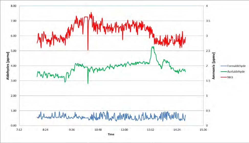
Figure 6: Ammonia and aldehydes concentrations in product gas during rapid load change test.
5. Discussions
The reported dry basis purity of CO2 of 99.9% is very high and in accordance with other references reporting purity of 99.6-99.8% from post combustion capture by chemical absorption processes [3]. The CO2 product gas leaving the stripper overhead system will always be water saturated at the pressure and temperature in overhead reflux condenser and receiver. For transportation purpose, a drying unit will almost always be required downstream the capture unit. The final saturation degree, dictating the design of the drying system, will be set by compressor and intercoolers configuration. The amount of water to be handled by downstream systems is not an inherent feature of post combustion, but rather a choice of operational settings, and is therefore not reported explicitly as an impurity in this work.
Nitrogen is found to be the impurity with highest level in the product gas, regardless of flue gas source, operational condition or solvent condition with concentrations ranging from 200 to 400 ppmv. Nitrogen can arise from entrainment of gas bubbles in the rich solvent flow from the absorber or possibly from NOX conversion. Other non-condensables reported from the Airborne analysis were O2 and Ar, where the sum was ranging from 10-50 ppmv. Presence of non- condensables at higher concentrations could have an adverse effect on operation of rotating equipment in the downstream compression and liquefaction part of the value chain, as they will influence the phase envelope characteristics. In particular, the presence of gas bubbles in liquid CO2 could cause increased vibration on CO2 injection pumps.
Ammonia concentration in the CO2 product gas has during the MEA campaign at TCM varied with the solvent quality. In general, the ammonia levels throughout the campaign has been low (< 10 ppmv). However, in periods where the solvent contained relatively high amounts of degradations products, e.g. prior to reclaiming operation, the ammonia emissions occasionally exceeded 60 ppmv. At these elevated concentrations there is a risk of solids formation downstream the stripper, such as ammonium carbamate, carbonate and bicarbonate as CO2 reacts with NH3. This was experienced at TCM, observed by increased pressure drop over the pressure control valve at the outlet of the condenser receiver vessel. Restricted flow and lack of operability of the pressure control valve caused plant shut down. Upon opening the control valve, salt precipitation was evident in the valve trim, restricting the flow and causing the high pressure drop. Such precipitation could also be a safety concern, if salts block impulse and feed lines to pressure safety valves that protect the stripper and overhead system. This is in particular valid for uninsulated and non-heat traced piping. Moreover, ammonia is reported [11, 12] to have an adverse effect on molecular sieve dehydration systems if deployed downstream, as it weakens the binding structure of sieves. No recommended threshold value was found reported in the literature.
Similar to ammonia, acetaldehyde concentration seems to correlate with the solvent quality. Formaldehyde seems to be less sensitive to the solvent condition with reported concentrations smaller than 1 ppmv. In general, the acetaldehyde concentration has been smaller than 10 ppmv throughout the campaign, whereas elevated concentration up to 15-20 ppmv was experienced in periods with increased degradation products and metal concentration in the solvent.
Amines were not detected from the samples analyzed by Airborne Labs, consistent with results from TCM lab analysis and FTIR online instrumentation. Based on analysis of MEA in liquid phase in reflux receiver drum and vapor pressure considerations, the expected MEA vapor phase concentration should be virtually zero. The design of the overhead condenser receiver at TCM is equipped with a wire mesh pad. The overhead receiver drum is common for both stripper configurations, which means that the load and consequently the separation efficiency is excepted to vary and some entrainment cannot be ruled out, although not found by the sampling probes in this study. In general, separation drums will not be 100% efficient and some liquid carry-over is to be expected, and design considerations of downstream systems should be made to include traces of amines. Consequently, trace levels over time will damage and reduce the lifetime of a molecular sieve used for drying, if constant carry-over is experienced.
6. Conclusions
After evaluating several months of operational data from the recent MEA campaign, it is evident that the CO2 product gas is rather unaffected by flue gas source and process conditions dictating the capture rate. CO2 concentrations of 99.9 v/v% on dry basis was obtained with nitrogen being the major impurity.
Among the impurities identified and analyzed for, ammonia, formaldehyde and acetaldehyde stand out as compounds not commonly reported in the literature. The solvent quality, in terms of metal content and amount of degradation products, seems to be the most influential parameter on the concentrations of acetaldehyde and ammonia the CO2 product gas. In addition, the ammonia slip was found to be correlated with temperature of the overhead stripper system.
High ammonia emissions were experienced in periods where plant was operated with a highly degraded solvent. For ammonia concentrations exceeding 60 ppmv, precipitation of salts as ammonia combines with CO2, caused operational upsets in the stripper overhead system due blocking and extensive pressure drop. Hence, special considerations for solvent quality management should be given with respect to ammonia emissions from CO2 stripper. It should be noted that the presented results are only typical and valid for MEA and the process parameters at TCM.
The variation of the measurements suggests that the limitation of the trace compounds in the CO2 product is challenging and sensitive to many parameters. This is also likely to be valid for other amines.
Acknowledgements
The authors gratefully acknowledge the staff at TCM DA, Gassnova, Equinor, Shell and Total for their contribution and work at the TCM DA facility. The authors also gratefully acknowledge Gassnova, Equinor, Shell and Total as the owners of TCM DA for their financial support and contribution.
Appendix A. Airborne Lab International analysis details
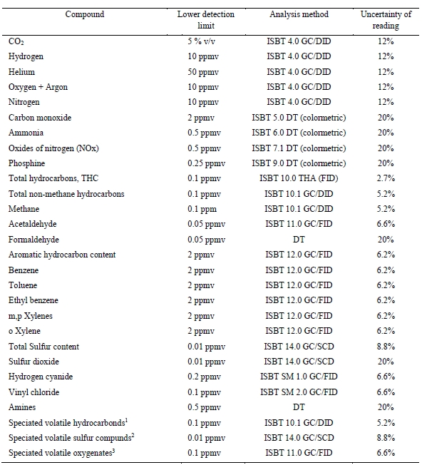
Table 6: CO2 product analysis provided by Airborne labs.
1Ethane, Ethylene, Propane, Propylene, Isobutane, n-Butane, Butene, Isopentane, n-pentane, Hexanes+
2Hydrogen sulfide, Carbonyl sulfide, Methyl mercaptan, Ethyl mercaptan, Dimethyl sulfide, Carbon disulfide, t-Butyl mercaptan, Isopropyl
mercaptan, n-Propyl mercaptan, Methyl propyl sulfide, 2-Butyl mercaptan, i-Butyl mercaptan, Diethyl sulfide, n-Butyl mercaptan, Dimethyl disulphide
3Dimetyl ether, Ethylene oxide, Diethyl ether, Propionaldehyde, Aceton, Methanol, t-Butanol, Ethanol, Isopropanol, Ethyl acetate, Methyl ethyl ketone, 2-Butanol, n-Propanol, Isobutanol, n-Butanol, Isoamyl alcohol, Isoamyl acetate
References
- The open-source centre at TCM, https://catchingourfuture.com/
- de Visser E, Hendriks C, Barrio M, Mølnvik MJ, de Koeijer G, Liljemark S, Le Gallo Y. Dynamis CO2 quality recommendations. Int. Journal of Greenhouse Gas Control, Vol. 2, Issue 4, 2008, p. 478-484
- Porter RTJ, Fairweather M, Pourkashananian M, Woolley RM. The range and level of impurities in CO2 streams from different carbon capture sources. Int. Journal of Greenhouse Gas Control, Vol. 36, 2015, p. 161-174
- Abbas Z, Mezher T, Abu-Zahra MRM. Evaluation of CO2 Purification Requirements and the Selection of Processes for Impurities Deep Removal from the CO2 Product Stream. Energy Procedia, Volume 37, 2013, p. 2389-2396,
- DNVGL-RP-F104. Design and operation of carbon dioxide pipelines, 2017
- IEA GHG. Impact of CO2 impurity on CO2 compression, liquefaction and transportation. Report 2016/01, April 2016
- Faramarzi L, Thimsen D, Hume S, Maxon A, Watson G, Pedersen S, Gjernes E, Fostås B, Lombardo G, Cents T, Morken AK, Shah MI, de Cazenove T, Hamborg ES. Results from MEA testing at the CO2 Technology Centre Mongstad: Verification of baseline results in 2015. Energy Procedia, Volume 114, 2015, p.1128-1145
- Gentry PR, House-Knight T, Harris A, Greene T, Campleman S. Potential occupational risk of amines in carbon capture for power generation. Int Arch Occup Environ Health (2014) 87:591–606
- Morken AK, Pedersen S, Nesse SO, Flø NE, Johnsen K, Feste JK, de Cazenove T, Faramarzi L, Vernstad K. CO2 capture with monoethanolamine: solvent management and environmental impact (GHGT-14, 2018)
- Lombado G, Shah MI, Fostås B, Hvidsten OA, Faramarzi L, Cazenove TD, Lepaumier H, Rogiers P. Results from aerosols measurement in amine plant treating gas turbine and residual fluidized catalytic cracker flue gases at the CO2 Technology Centre Mongstad (GHGT-14 ,2018)
- Kempra J, Sutherland L, Watt J, Santos S. Evaluation and analysis of the performance of dehydration units for CO2 capture, Energy Procedia 63 (2014) p. 7568 – 7584
- Purcell T. Effects of Contaminants on Molecular Sieves, Hydrocarbon Engineering, 1997
- Morken AK, Pedersen S, Kleppe ER, Wisthaler A, Vernstad K, Ullestad Ø, Flø NE, Faramarzi L, Hamborg ES. Degradation and Emission Results of Amine Plant Operations from MEA Testing at the CO2 Technology Centre Mongstad, Energy Procedia 114, 1245-1262